What's new
Van's Air Force

Don't miss anything! Register now for full access to the definitive RV support community.

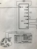
Wiring the ACS510-2 to PMags

rockitdoc

Well Known Member
Sponsor
If anyone has done this with two PMags I would appreciate a diagram showing the connections. I thought I understood how that switch works, but after going around it with my voltmeter, I am not so sure, now.
 
I have that set-up in my RV6, although it is a 25 year old version of the switch.

Does this picture help at all? I don't know what note 1 and 2 are, but for PMAGs you don't want the jumper between GRD and R.

Check the terminal labels on the back though. I believe there are other versions of the switch, where the S and BAT terminals are reversed from what is in the picture.
 

Attachments

  • A510 pic 1.jpeg
    A510 pic 1.jpeg
    643.4 KB · Views: 55
Last edited:
I have that set-up in my RV6, although it is a 25 year old version of the switch.

Does this picture help at all? I don't know what note 1 and 2 are, but for PMAGs you don't want the jumper between GRD and R.

Check the terminal labels on the back though. I believe there are other versions of the switch, where the S and BAT terminals are reversed from what is in the picture.

Now, I'm really confused. :)

Maybe if I saw the rest of the picture.
 
The box at the bottom indicates how the switch works, which I thought was the primary question. That and Steve's picture describe the set-up.

R goes to the Right mag (or PMAG)
L goes to the Left mag (or PMAG)
Bat goes to 12V somewhere
GRD goes to ground somewhere
S goes to the starter contactor
 
Here is my diagram for the PMAG ignition system on my RV-7A. I used shielded wire to cluster wires together; belt and suspenders. I also use a combined Switch Breaker for testing the internal generators at runup, instead of a breaker and separate switch.

The key switch wires are not completely detailed on this image.
 

Attachments

  • ExpressSCH PMAG Ignition.pdf
    47 KB · Views: 117
Back
Top