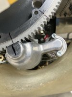
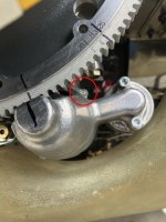
I am trying to find the alignment position of the TC mark on the flywheel to the starter motor. People in the field is saying the reference timing mark is at the black line shown in the picture. Other said the reference mark should be to line up the TC mark on the back of the flywheel to the middle engine case. So what should be the correct alignment to use? From the position in the photo, the mark in the back of the flywheel is off the centerline of the case
Thanks
Thanks