What's new
Van's Air Force

Don't miss anything! Register now for full access to the definitive RV support community.

Temperatures experienced by plenum?

noahhl

Member
Anyone have any data on the temperatures experienced by the underside of a plenum (on an IO-320, to be precise, but I'd take any data points). Obviously will vary based on deck height, airflow, etc, but anything would be helpful. Considering some...alternative materials and trying to figure out how bad an idea it is.

Thanks!

Noah
 
Anyone have any data on the temperatures experienced by the underside of a plenum (on an IO-320, to be precise, but I'd take any data points). Obviously will vary based on deck height, airflow, etc, but anything would be helpful. Considering some...alternative materials and trying to figure out how bad an idea it is.

Not much above OAT in flight. Well above 200F after shutdown, for sure on a hot day.
 
Not much above OAT in flight. Well above 200F after shutdown, for sure on a hot day.

Thanks!

Toying with 3d printing using PA12+CF, which claims softening and deflection temperatures in the 375F range. So perhaps it's not impossible...

I can easily do a traditional fiberglass or carbon fiber layup -- I have a CAD model of the plenum and a CNC to make a plug or mold with. I'm definitely just doing a basic lid to start, but got to dreaming about the potential to experiment down the line with more complicated structures (think F1 floors).
 
My experience on a very hot day, 104 deg.F, the plenum temp. after shutdown was at, or around, 230deg. F. ( going off memory here)at its highest. The worst case scenario was facing away from the wind, shut down.
If the prop was turning at all, or if the aircraft was facing into even a slight breeze, those temps plummeted.
This is for an IO360 with standard rubber seal to cowl construction.
 
I always thought the best way to make a plenum would be to make a layup of the underside of the upper cowling, then use that as the “lid” of the plenum, just set it an inch or so below the cowl, allowing for engine shake. Seems this would maximize the volume inside the plenum to allow for the air to expand and slow down.
 
My experience on a very hot day, 104 deg.F, the plenum temp. after shutdown was at, or around, 230deg. F. ( going off memory here)at its highest. The worst case scenario was facing away from the wind, shut down.
If the prop was turning at all, or if the aircraft was facing into even a slight breeze, those temps plummeted.
This is for an IO360 with standard rubber seal to cowl construction.

Thanks for the data point! Seems like some testing is in order to see if the nylon CF actually holds up in the 250-300 range as advertised.

I always thought the best way to make a plenum would be to make a layup of the underside of the upper cowling, then use that as the “lid” of the plenum, just set it an inch or so below the cowl, allowing for engine shake. Seems this would maximize the volume inside the plenum to allow for the air to expand and slow down.


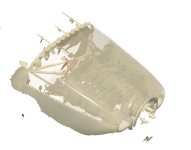
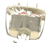
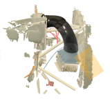
This is basically what I'm doing, except starting digitally. I 3d scanned the engine w/ plenum and lower cowling on, and separately scanned the upper cowl. A little reconstruction work to put them together in CAD and I can create an exact offset of the cowl, construct ducts that perfectly fit the inlets, etc. Fabrication is the remaining question -- do I CNC cut molds or plugs, or 3d print?

(Yes, this is overkill. Experimental aviation.).
 

Attachments

  • 2023-11-13 17_08_41-Autodesk Fusion 360.png
    2023-11-13 17_08_41-Autodesk Fusion 360.png
    402.5 KB · Views: 34
  • 2023-11-13 17_09_40-Autodesk Fusion 360.png
    2023-11-13 17_09_40-Autodesk Fusion 360.png
    534.8 KB · Views: 47
Very impressive. Keen to see how it goes.
I went the plenum route (there’s a thread somewhere about it) as well.
Made my plug from the top of the cowl. Then a mold.
Worked well. I used an easy to get vinylester resin and did a vacuum infusion.
I reasoned that the in flight temperatures would be well below transition temp and that as said above only gets hot at shutdown. I have some RTDs floating around so one of these days I may try to measure it more accurately.
It’s exhibited no signs of heat stress so far at about 250h.
 
Plenum

You obviously have the skills and a good plan.
I always wanted to make a new plenum by laying up the lid on the inside of the cowl. The inlet ramps are the tricky part. Your plan should yield a really nice plenum.
Mine was a vendor plenum. I could have made three in the time it took to make it fit. Oh well. Next time.
 
Has anyone ever made separate left and right plenums? Just directing the air around the cylinder finned areas, not covering the top of the casing. There's a drawing of this arrangement in one of Bingelis's books, but I've never seen one for real.

I was wondering whether that might have some advantages for controlling the airflow around the cylinders. It might also help with plenum stiffness if it starts to soften at high temperature after shutdown, since there's much less unsupported area to sag.

Has anyone seen such a beast in the flesh, or does anyone know why it might be a really bad idea?
 
I always thought the best way to make a plenum would be to make a layup of the underside of the upper cowling, then use that as the “lid” of the plenum, just set it an inch or so below the cowl, allowing for engine shake. Seems this would maximize the volume inside the plenum to allow for the air to expand and slow down.

Years ago, I converted my standard RV baffling/seals and cowl to a Sam James plenum and cowl. Instructions were to place the plenum as low as possible.

My oil temps went from ideal to high and I ended up installing a 13 row oil cooler. I truly believe that the plenum volume reduction was responsible. A classic example of Bernoulli’s Principal.

As a side note, I lost a dollar bet with DanH that I would gain 10 knots from the conversion. I gained 8 knots in cruise. I finally paid the debt at the beer fest at OSH this year when I saw him in person for the first time.

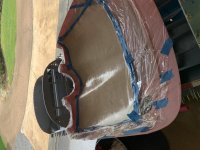
I still plan to have a plenum on the 8. Only this time the lid will be much higher and the cowl the mold. And here’s my start.
 

Attachments

  • IMG_5974.jpg
    IMG_5974.jpg
    445 KB · Views: 37
  • IMG_5984.jpg
    IMG_5984.jpg
    475.3 KB · Views: 31
Thanks for the data point! Seems like some testing is in order to see if the nylon CF actually holds up in the 250-300 range as advertised.

This is basically what I'm doing, except starting digitally. I 3d scanned the engine w/ plenum and lower cowling on, and separately scanned the upper cowl. A little reconstruction work to put them together in CAD and I can create an exact offset of the cowl, construct ducts that perfectly fit the inlets, etc. Fabrication is the remaining question -- do I CNC cut molds or plugs, or 3d print?

(Yes, this is overkill. Experimental aviation.).

Just as a data point for you, I went down a very similar path. 3d scan of engine and cowl——> CAD plenum design —-> CNC female mold plug —>female mold—> plenum layup.

I laid up up the plenum in carbon fiber with Premium Resin Tech’s RDR 3350 (450 F max). I have about 75 hours on it. I am pleased with the results and I have not seen any distortion.

One of the concerns I might have about 3d printing is the shrinkage factor when printing a relatively large item. I suspect that the final dimensions won’t match the CAD very closely. Although if you know the exact shrink factor, you might get close enough if you account for it. I’m sure there are now 3d print methods that address this, but I went the other way and I’m pleased with my result.

Kudos to you for taking this on.
 
Last edited:
This is basically what I'm doing, except starting digitally. I 3d scanned the engine w/ plenum and lower cowling on, and separately scanned the upper cowl. A little reconstruction work to put them together in CAD and I can create an exact offset of the cowl, construct ducts that perfectly fit the inlets, etc. Fabrication is the remaining question -- do I CNC cut molds or plugs, or 3d print?

Not overkill if you know well that some modifications will be needed. And they may. I made my plenums from the inside of my 7 cowl, and make calculations transferred to a buck for the inlet diffusers. I sure wish that I had 3D scan of my bucks, I have a great design w/documentation of performance that is sitting on my shelf. Kinda shameful. You would be welcome to scan them if you wish. Collaboration would be fun!

You asked about implementation - I would suggest 3D print some shell/molds for making fiberglass parts.

I tried to quote the Aussie question on split plenums - but here goes - - I have seen and have photos of said used in Reno racing. It is likely a more extreme version and not sure normal mortals would ever measure benefits. Things you have to consider - flow for oil cooler, cooling of case and other under cowl parts. There is a long and short diffuser due to cylinder offset so tuning may be needed to match - more development. I do not believe the larger plenum volume is better theory, but the lower volume means more required internal flow knowledge and management. The larger plenum theory once existed for engine intake and exhaust manifolds, but that was debunked in the 80's. Lots of thermo and fluid flow reasons.
 
Bill's plenum has excellent inlet ducting, assuming a desire to go with a prop shaft extension and internal diffusion. There's also the external diffusion choice, which requires no ducting or lid, and can operate with a short cowl. Both work. Each has its strengths.

Recent articles have focused on internal diffusion, but external is actually very common in GA...some popular Cessna models, the Mooney Acclaim, and a bunch of others.
 
Has anyone ever made separate left and right plenums? Just directing the air around the cylinder finned areas, not covering the top of the casing. There's a drawing of this arrangement in one of Bingelis's books, but I've never seen one for real.

I was wondering whether that might have some advantages for controlling the airflow around the cylinders. It might also help with plenum stiffness if it starts to soften at high temperature after shutdown, since there's much less unsupported area to sag.

Has anyone seen such a beast in the flesh, or does anyone know why it might be a really bad idea?

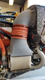
A few photos I had in my files, no information on how they worked out.
 

Attachments

  • 45020414_2235850089995221_4569943660774293504_o-1.jpg
    45020414_2235850089995221_4569943660774293504_o-1.jpg
    277.3 KB · Views: 43
  • 45124861_2235850143328549_6500633616123428864_o-1.jpg
    45124861_2235850143328549_6500633616123428864_o-1.jpg
    345 KB · Views: 37
..............Toying with 3d printing using PA12+CF, which claims softening and deflection temperatures in the 375F range.....

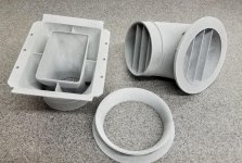
Three years ago I installed an oil cooler duct assembly which is PA12 (non-filled), and it's held up great. No deflection that I can tell (the bolt preload remains tight, and that's good evidence it isn't moving). So, I think your plan for using PA12+CF is a good one.

20201015_153358.jpg20201012_210730.jpg 20201014_102501.jpg
 
Years ago, I converted my standard RV baffling/seals and cowl to a Sam James plenum and cowl. Instructions were to place the plenum as low as possible.

My oil temps went from ideal to high and I ended up installing a 13 row oil cooler. I truly believe that the plenum volume reduction was responsible. A classic example of Bernoulli’s Principal.

As a side note, I lost a dollar bet with DanH that I would gain 10 knots from the conversion. I gained 8 knots in cruise. I finally paid the debt at the beer fest at OSH this year when I saw him in person for the first time.

I still plan to have a plenum on the 8. Only this time the lid will be much higher and the cowl the mold. And here’s my start.

Looks like a great start!! I stole the idea from Mike Patey to take a mold off the underside of the cowl.. it was in one of his “Scrapy” build videos on YouTube.
 
Three years ago I installed an oil cooler duct assembly which is PA12 (non-filled), and it's held up great. No deflection that I can tell (the bolt preload remains tight, and that's good evidence it isn't moving). So, I think your plan for using PA12+CF is a good one.

View attachment 51125View attachment 51120 View attachment 51121

Too often 3D printing looks like using a sledgehammer to kill flies...but then something like this comes along. Beautiful work sir. I'm ok with glass, but this much detail would take a while.
 
I sure wish that I had 3D scan of my bucks, I have a great design w/documentation of performance that is sitting on my shelf. Kinda shameful. You would be welcome to scan them if you wish. Collaboration would be fun!

I'd love to! Someday when the plane is done I'll come out there (or if anyone has a plenum they think is great and wants to fly to KAGC, I've got a scanner and space in the hangar).

Three years ago I installed an oil cooler duct assembly which is PA12 (non-filled), and it's held up great. No deflection that I can tell (the bolt preload remains tight, and that's good evidence it isn't moving). So, I think your plan for using PA12+CF is a good one.

That's actually the first project along these lines -- your diffuser (thanks!), ducting to fit my geometry. Test prints in cheap plastic going now.
 

Attachments

  • 2023-11-14 18_21_39-Autodesk Fusion 360.png
    2023-11-14 18_21_39-Autodesk Fusion 360.png
    505 KB · Views: 26
...... Beautiful work sir. I'm ok with glass, but this much detail would take a while.

Thanks! Yeah, without turning vanes it would have been a toss-up between growing and laminating it. I'm OK with composites too; I built a carbon-fiber EFI intake manifold for my GTO 25 years ago, but I really like the design flexibility of growing parts (3d printing as the kids call it now).

...That's actually the first project along these lines -- your diffuser (thanks!) ....

Ah, that's right! You're welcome!
 
I always thought the best way to make a plenum would be to make a layup of the underside of the upper cowling, then use that as the “lid” of the plenum, just set it an inch or so below the cowl, allowing for engine shake. Seems this would maximize the volume inside the plenum to allow for the air to expand and slow down.

I've recently done that, it is worth figuring out exactly what part if the cowl sits above the cylinders. The rear baffle was shrinked/stretched to match the top. For the front centre I moulded the piece matching the plenum lid in glass and riveted to a aluminium plate around the front of the case. The front ramps matching to the inlet was more of a challenge which I moulded on the aircraft using sheet wax. I found I couldn't drop the plenum very much and had to bump the top cowl around the forward cylinder heads (angle valve motor in an RV-6). I was going to seal the plenum to the cowl inlets but didn't and have really cool temperatures (oil 190, CHT 320) so am not going to. I am also not going to paint or polish it - I have a couple of areas that rub occasionally on the inside of the cowl so it would be a waste of time - and very few people would see it!
 
Back
Top