What's new
Van's Air Force

Don't miss anything! Register now for full access to the definitive RV support community.

radio stack cutout width

bmellis11

Well Known Member
Sponsor
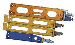
I will be installing a GTN 750xi and GMC507 (autopilot controller) in the radio stack of my RV-8 panel. I'm currently designing the panel in Solidworks. I want the mounting trays to be behind the panel and want the bezel of the devices to cover any gaps between the radio stack cutout and the equipment.

Based on the Garmin installation manuals and what I was able to find in old posts, the recommended cutout width for the radio stack is 6.25". But measuring the equipment bezel width in Solidworks, I see that it is also 6.25". So there's no room for tolerance in the cut if I want to hide the gaps.

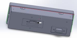
My question is whether any of you guys have experience reducing the width of the radio stack cutout to say 6.18" so that the bezel will definitely cover the gap. I assume the tabs on the side of the GMC507 in the attached picture can be pushed in to fit the equipment all the way in?
 

Attachments

  • Screenshot 2023-11-21 160825.png
    Screenshot 2023-11-21 160825.png
    268.1 KB · Views: 88
I've cut two panels for Dynon equipment and the way I ensured that the narrow bezels covered the gap was to initially make the cutout slightly under-sized and then final size it with the actual equipment. The process is to file a bit off, trial fit, repeat until it just fits nicely.
 
Not sure of the exact width but the 507 shouldn't be an issue since you can install it without a tray but the 750 may be an issue.

I am working on the panel in my 10 now and I know that some of the Garmin units need part of the tray to fit through the panel cutout. I don't have time now but I will try to find that info this evening
 
When I was fitting the radio stack in the RV-9A, 6.25" worked most of the time for most of the radios. Don't remember the gory details, but I do remember that not all my radios were exactly the same width. It was not pretty.

Hopefully somebody else can add details to my confusion.

Ed
 
Garmin install manuals give different cut out dimensions. One for mounting the tray from the front and a typically smaller dimension if the tray is installed from the rear.
Can’t speak to the 750 specifically but it wouldn’t hurt to look closely at the drawings.
 
Garmin install manuals give different cut out dimensions. One for mounting the tray from the front and a typically smaller dimension if the tray is installed from the rear.
Can’t speak to the 750 specifically but it wouldn’t hurt to look closely at the drawings.

This.
You want to mount the tray from behind. Only the bottom edge of the tray comes through the panel cutout. The other three edges butt up against the back of the panel. I made my panel cutout just marginally wider than the inside width of the tray. From memory the 6.25 is too big.

IMG_0806.jpeg
 
Another q regarding cutout dimensions: the Garmin manuals state specific heights for the cutouts (I'm using option 3 - installed from back of panel), but those cutouts are for a single unit. Is there any deviation when stacking multiple units on top of each other. My radio stack will consist of GNX375, GNC215, GTR200 and GMA245. Per the manuals the cutouts total height should be 5.81 inches, but when modelling it on OnShape using the Garmin cad drawings, I get to about 6 inches. My Cad model has all the units 'mated' with the dimples on the lower tray touching the dimple on the installation tray above it. Any experience here? I don't have the actual trays yet to measure...
Apologies the image shows 2x GTR200's as Garmin has not yet released the CAD for the GNC215.
I think the height difference is due to the heights of the 'dimples', which means that you cannot just add the heights from the Garmin installation manuals when planning your cutout.
 

Attachments

  • Screenshot 2024-02-06 at 08.30.07.png
    Screenshot 2024-02-06 at 08.30.07.png
    850.3 KB · Views: 39
Another q regarding cutout dimensions: the Garmin manuals state specific heights for the cutouts (I'm using option 3 - installed from back of panel), but those cutouts are for a single unit. Is there any deviation when stacking multiple units on top of each other. My radio stack will consist of GNX375, GNC215, GTR200 and GMA245. Per the manuals the cutouts total height should be 5.81 inches, but when modelling it on OnShape using the Garmin cad drawings, I get to about 6 inches. My Cad model has all the units 'mated' with the dimples on the lower tray touching the dimple on the installation tray above it. Any experience here? I don't have the actual trays yet to measure...
Apologies the image shows 2x GTR200's as Garmin has not yet released the CAD for the GNC215.
I think the height difference is due to the heights of the 'dimples', which means that you cannot just add the heights from the Garmin installation manuals when planning your cutout.
I found that the dimples didn’t always correspond. What worked well for me on both builds were “paddle pop sticks”
You guys call them tongue depressors or popsicle sticks.
They’re about 80 thou ish. Slip them in so they touch none of the dimples. When I modeled my stack in solidworks the second time I think I just used a constant offset excluding the dimples.
Given I then cut the holes manually it didn’t really make much difference.
1707201588668.jpeg
 
I don't remember the exact sizes I used because I modeled it in Fusion 360. One thing to make sure and take account of is the faceplates on the units, they usually overlap the racks a bit. That info should be in the manuals.
 

Attachments

  • IMG_1150.jpeg
    IMG_1150.jpeg
    398.8 KB · Views: 35
Try to give a little bit of vertical clearance between trays, more than the dimples (for those trays that have them). If you ever had a hard time removing a unit from a stack it is usually because the installer placed the trays too tightly vertically. Because the face bezels of the units are little taller than the trays and bind against each other. The cutouts in the manuals don't take into account the extra space required for clear contact of the bezels. I like to stack .020" aluminum sheet shims between the trays when I mock up a stack to give that little bit of extra service gap to avoid the subsequent stuck radio phenomena. Just like Richard's Popsicle Stick method shown above.
 
Back
Top