What I've found so far in my quest... (please feel free to pick these ideas apart, I'm quite open to improving my methodologies).
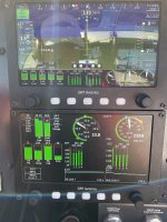
1) with GRT EIS-66R remote-mounted engine instrument the MAP sensor cannot be calibrated (confirmed in correspondence with Jeff DeFouw of GRT). I live with this error and manually subtract the 0.3" error from the displayed MAP
2) as a follow-on from 1), above, percent horsepower is also in error. After looking at the Lycoming power charts I've come up with a very rough rule of thumb. For low altitude operations between 60% & 80% power, every tenth of an inch of MAP error causes approximately a 1% error in indicated percent horsepower.
3) GRT makes no effort to include Fuel Flow in their percent horsepower calculations (confirmed through correspondence with Jeff DeFouw of GRT). With this in mind it is important to understand the GRT percent power indication is only accurate when the engine is running at "best power" mixture setting to match the data presented in the Lycoming power charts. The further we lean or enrichen beyond "best power" mixture, the more inaccurate the GRT percent power indication becomes.
,
4) This observation may (or may not) be unique to my particular O-360 (carb'd). The harder I run the engine the more uniform the CHT and EGT become. If I'm just dawdling around at 55% or 60% power I see large spreads in temperatures. If I push the power up to a true 75% the temperatures are almost a flat line across the screen.
I hope this information is at least somewhat helpful to others.
Interesting comments. Agree if GRT (which I have) calculates % power based on Lycs look up table based on MAP and RPM for best power, leaner or richer will be less power.
Carbs typically you can expect (not always) have less even EGT between jugs, but not always. FI can off injector mismatch and carbs sometimes hit a golden balance. Some find a slight application of carb heat can be used to balance carb'ed engine EGTs, your mileage may vary, pun intended. I don't think it is heat as much as the turbulence into the airbox may re-balance the flow. Carb has fuel air mixture going all the way through runner, and it starts out theoretically even before being divided 4 ways. However each jug has different intake port/valve characteristics due to manufacturing tolerances.
YES you will get uneven EGT on Carbs at lower power if the throttle is partly closed. The butterfly will bias fuel between the fwd vs rear bank of two intake runners. This is why it is BEST to fly above 8,000' (8500' or 9500' VFR hemispherical alt rules). This allows FULL wide open throttle, sub 75% allowing leaning.
Some boundary conditions on CHT and % power
- No leaning above 75% power
- CHT and OT are Limiting factors not EGT
- RV design and build: Oil cooler, cowl, baffle, setup, installation deficiencies
- Ambient temps.
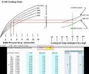
So question what does % power mean (example GRT EIS). Mostly I see MAP and RPM as the driving variables. But you bring up a good point. Are you at best power (mixture) or economy (leaner). The difference can be small or well over 10%. But the reading will always be MAX, which is good.
Looking at the chart, with some assumptions it can be as much as 10% or more less power from best power mixture to ECON or over rich. So the good news is if you are leaning your indicated % power is higher than actual. Also if way over rich your % power indicated (GRT) is also going to be higher than actual. Great point. Of course we never want to be over rich (unless you are trying to cool your engine) and we want to lean with respect to the above boundary conditions and limits.
So if operating Rich of Peak (best power) or close, GRT % power is accurate. If LOP or way too rich, depending on altitude you could be 10% or much more lower than indicated % power on GRT EIS.
When I was a young pilot and feeling my wings, going on long distant cross country flights, I had to cross the Cascades typically if going EAST. So to top the range was +9000 feet. So right to +9,500 to 11,500 feet in small (low powered planes) was common. You can fly lower or even through the mountain passes below 6,000'. If you takeoff and don't lean as you climb at least starting at 8000 feet, you no climb-mee, at least to desired altitude. Keep in mind late 80's, GA plane, had RPM no MAP gauge, no fancy 8 channel CHT/EGT engine monitor. Once I realized I was not able to climb. you would not get to altitude.... I realized on one flight I could not climb well. Engine was drowning in fuel. I realized my error and leaned and POWER went up. Go figure.
Inaccurate indicated % power is critical only for rule #1, no leaning above 75 percent power. For the most part a GRT type derived MAP + RPM percent power indication will give you a safe point to start leaning. Again CHT and OT are also key and YOU MAY want to have an overly rich mixture for engine cooling. MOST of all you want to prevent a lean mixture at high power for detonation prevention which can be destructive to engine. I know most of you all know this but to the few which may be coming up in aviation may not know.