What's new
Van's Air Force

Don't miss anything! Register now for full access to the definitive RV support community.

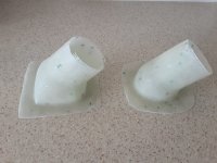
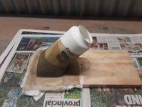
My first foam mold part - 60 degree 2" duct elbow

What advantage does that provide over putting a 60-degree bend in the scat tube?

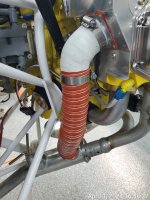
For my vertical draft engine, adding this 60 degree elbow eliminates the need for the clamp to keep the flexible duct which runs between baffles and heat muff from rubbing the engine mount weldment. I simply find this more elegant. Adds to build time. Increases composite fabrication skills. Gratifies the soul.

For RV-7 and -7A vertical draft (which almost always means carbureted, exception is IO-320-D1A which is vertical draft, and my Continental Titan which is SDS) ref dwg OP-29 (I have rev 2). It’s not well shown but the clamp in zone A10 keeps the flexible duct from rubbing the engine mount weldment.

For RV-7 and 7A horizontal induction cabin heat air is taken not from the right rear baffle but from the right front inlet ramp of the baffles so the situation is different, ref OP-33 (I have rev 2). In this dwg such a clamp is shown more clearly in zone C9 although it’s for the flexible duct from heat muff to cabin heat valve.

None of this is cast in stone due to variations in exhaust, heat muff, mufflers, space-time continuum and I don’t know what all else.
.
 
Last edited:
I
For my vertical draft engine, adding this 60 degree elbow eliminates the need for the clamp to keep the SCAT which runs between baffles and heat muff from rubbing the engine mount weldment. I simply find this more elegant. Adds to build time. Increases composite fabrication skills. Gratifies the soul.

For RV-7 and -7A vertical draft (which almost always means carbureted, exception is IO-320-D1A which is vertical draft, and my Continental Titan which is SDS) ref dwg OP-29 (I have rev 2). It’s not well shown but the clamp in zone A10 keeps the scat tube from rubbing the engine mount weldment.

For RV-7 and 7A horizontal induction cabin heat air is taken not from the right rear baffle but from the right front inlet ramp of the baffles so the situation is different, ref OP-33 (I have rev 2). In this dwg such a clamp is shown more clearly in zone C9 although it’s for the SCAT from heat muff to cabin heat valve.

None of this is cast in stone due to variations in exhaust, heat muff, mufflers, space-time continuum and I don’t know what all else.
.
I also think it's a good idea because I did much the same thing for the oil cooler that is on the firewall and fed by a SCAT hose from the baffle behind cylinder #4.

What is the SCAT type and source in your photo? I recently got some that looks similar and it is not as flexible as the SCAT that came from Van's many years ago.


20240322_091800.jpg20240320_184334.jpg
 
… What is the SCAT type and source in your photo? I recently got some that looks similar and it is not as flexible as the SCAT that came from Van's many years ago.
Hi Paul,

It is SCEET from Aircraft Spruce.

An informative video IMO:
.
 
Last edited:
Hi Paul,

It is SCEET from Aircraft Spruce.

An informative video IMO:
.
It's an informative video, though he says to use SCEET for the engine inlets and to avoid SCAT because the wire can rust and break off and get sucked into the engine. My understanding is that SCEET must only be used in situations of positive pressure and that SCAT must be used where there is suction, e.g. carb heat inlet duct. This is due to the risk of the SCEET inner lining delaminating and getting sucked in.
In either case, hopefully the condition inspection will pick up any signs of degrading ducts.
 
Back
Top