What's new
Van's Air Force

Don't miss anything! Register now for full access to the definitive RV support community.

Lycoming camshaft Inspection question

Cardinal767

I'm New Here
Question for the Lycoming experts about the camshaft inspection operations.
With the Lycoming limits to seeing the camshaft and having to remove a cylinder to do so, has anyone tried a different method?

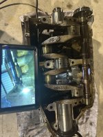
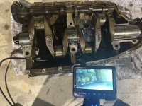
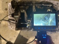
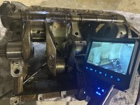
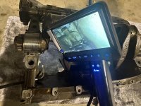
Having a new articulating borescope to play with and having looked at the anatomy of the crankcase of my IO-360-A1B, I see another possibility.

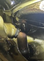
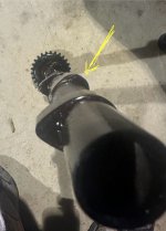
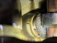
What are the problems with removing either (or both) the fuel pump and/or prop governor to put the borescope through the openings in the back of the crankcase and working it forward to access all the cam lobes and the faces of the followers?

I’m not sure if mechanical fingers through the the cylinder oil return fittings could help guide the camera.

It all sounds easier than pulling a cylinder. Or maybe not?
 
I did it by removing the sump. You should be able to see three lobes in the back, The rest are probably in the same condition. If you are looking for corrosion.
I found non
My luck varies Fixit
 
I believe removing #1 or #2 cylinder is the easiest option. You do need cylinder wrenches though. No need for ring compressor if you can slide pin out and keep piston in jug...assuming there's limited varnish on pin.
 
Thank you for the suggestion. I started changing the oil today and decided to try to see what I could see by removing the AC fuel pump. After a little work I was able eventually work the borescope forward enough to see the cam lobes. I used a borescope with two cameras, which helped me me keep my bearings. Since #1 and #2 cylinder shared one lobe and the both required the max length pushrod to meet the tappet clearance limit, that was my target. I saw just enough of the tappet body face to warrant pulling a cylinder for a better look. After pulling a cylinder and seeing the damage, the engine came off! The pictures say it all.
Please note, the engine ran smooth but the big clue after reviewing my data was that the Gami spread was getting larger the last few months. #3 and #4 were well LOP before I would get #1 and #2 LOP. The higher the altitude the worse the spread was. Now to stand in line for engine work.
 

Attachments

  • IMG_6661.jpeg
    IMG_6661.jpeg
    760.5 KB · Views: 144
  • IMG_6662.jpeg
    IMG_6662.jpeg
    510.9 KB · Views: 145
  • IMG_6663.jpeg
    IMG_6663.jpeg
    1.5 MB · Views: 141
  • IMG_6658.jpeg
    IMG_6658.jpeg
    1.1 MB · Views: 146
Pretty drama pictures! I second Dan’s question, if you were doing oil analysis, did you see any trends?

Also, which borescope do you have?

-jim
 
Yes, there was a small trend up but sadly I normally take a sample every other oil change but didn’t take a sample the last two oil changes, AKA 10 months. I did find serval tiny “flakes” of metal in the oil filter at the last oil change and followed the Lycoming instructions on counting the pieces. The evidence was there, I will admit I responded slowly to it. Lesson learned.
 
Any metal in your oil filter or screen over the years? Your cam lobe and lifters look exactly like my #3 & #4 intakes, I had increasing metal in my oil filter for 600 hours. I finally confirmed it was time to overhaul the bottom end by measuring the valve lift which turned out to be off by about 40% on the two affected cylinders.0902221404b.jpg
 
Yes, there was a small trend up but sadly I normally take a sample every other oil change but didn’t take a sample the last two oil changes, AKA 10 months. I did find serval tiny “flakes” of metal in the oil filter at the last oil change and followed the Lycoming instructions on counting the pieces. The evidence was there, I will admit I responded slowly to it. Lesson learned.
Again, thanks for the feedback. Guess we never ever stop learning, the more so in aviation.
 
Yes, I was getting more and more metal in the filter and oil testing. Then came the tiny flakes in the filter. Here is the borescope and path I took with the fuel pump removed. Hope this helps everyone visualize the path. Yes, the connecting rods are off but I was able to position things with some trial and error to get all the way forward
 

Attachments

  • IMG_6680.jpeg
    IMG_6680.jpeg
    1.8 MB · Views: 60
  • IMG_6679.jpeg
    IMG_6679.jpeg
    2.5 MB · Views: 56
  • IMG_6678.jpeg
    IMG_6678.jpeg
    2.4 MB · Views: 51
  • IMG_6675.jpeg
    IMG_6675.jpeg
    2 MB · Views: 47
  • IMG_6674.jpeg
    IMG_6674.jpeg
    2.2 MB · Views: 45
  • IMG_6682.jpeg
    IMG_6682.jpeg
    1.1 MB · Views: 44
  • IMG_6681.jpeg
    IMG_6681.jpeg
    2.4 MB · Views: 57
Back
Top