What I Did -
Larry -
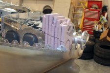
I too, used wetsuit material - the thickest I could find (mics @~ .250").
I cut the flat pattern so when the ends were drawn together for gluing (using neoprene wetsuit adhesive) the "shape" was a truncated cone, slightly smaller in diameter on the ends so that some "stretching" would have to take place for attachment/sealing. In addition to gluing the end faces, I also cross stitched, with Kevlar (can break it) thread, as a secondary line of support.
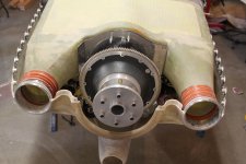
I also covered the joint area with clear silicone as a sealer against contaminant intrusion (read oil). I also put a layer of silicone on the end of the "coupling" I didn't want to move against its contact surface. You can just see the silicone "layer" on the inside of the 3rd pic. On that end (silicon side) I used a modified worm drive type hose clamp to increase the "foot print" on the contact area to give better bearing pressure over the area.
21+ years later - still going strong on the second set.
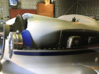
Space between inlet rings and plenum inlet ~ 3/8 - 1/2"
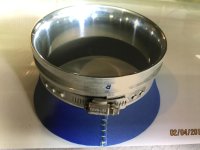
The last picture shows a smaller ring, as it is for the induction inlet.
HFS
HRII S/N 002