What's new
Van's Air Force

Don't miss anything! Register now for full access to the definitive RV support community.

James transit duct

Is there a specific limitation preventing the transit duct from being bonded to the backplate? Additionally, could there be advantages to introducing an aluminum plate between the backplate and the FM-200 for reinforcement purposes; are there some potential drawbacks or redundancy that I’m not seeing?
 

Attachments

  • IMG_6737.jpeg
    IMG_6737.jpeg
    101.9 KB · Views: 65
  • IMG_6736.jpeg
    IMG_6736.jpeg
    87.9 KB · Views: 72
Are you proposing to add the aluminum (.063"?) to stiffen the joint for sealing to the servo? Not a bad idea to bond the two together if you are not challenged in axial length. I put packing tape (waxed) on the servo, and created an RTV gasket to ensure a good seal.

Be aware of the direction the servo is pointing and that it is in the right place to meet the cowling inlet. The engine is typically rotated left, so it you already have the cowl fitted, and can ensure the alignment you can use some epoxy mix between the aluminum and fiberglass to make an alignment wedge. This way you can ensure the inlet cone will evenly compress the filter seal all the way around.
 
Thanks Bill! Yes, the addition of the aluminum would be to stiffen the joint, preventing any flex between the back plate and the servo. I was thinking 1/8” plate instead of 0.063 for flatness and rigidity.

The transit duct, if bonded, would require two holes which you can see in my first post, in order to access the attachment bolts. Do you think this would disrupt the air flow into the servo?
 
Mark, I was able to mount the flow inlet w/o drilling holes in it. I did not want the possibility of something going through the engine. I used a 1/4" bolt and machined down the head to allow enough room to fit within the back housing.

The flow inlet . . I fastened with screws to the back housing via small angle brackets epoxied with the screws located under the filter ring so they could not back out. It also stiffened the flow plate to carry compression loads of the filter seal.

Here is a photo, note the bolt head showing under. The dark area in the center is a flox backing to mate/align with the servo inlet. Be sure to check the opening of the alternate air door for interference.

IMG_2179.jpg
 
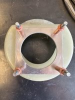
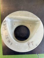
You are absolutely right about not wanting anything to have a chance of going through the engine, so I'm going to copy your design. I was looking at how Dave Hock had designed his intake, and that's where I came up with the idea to bond them together. He sure does some nice work!! I understand how you used the small angle to attach the flow inlet and the back housing.....I'm going to copy your design there, too. I am designing the alternate air the same way Dave did his (thanks Dave for posting your pics!!).

I have the ability to machine the an aluminum plate to pretty precise angles to line up the servo inlet. I'm going to attempt to to this, and if I can't, I'll do it the same way you have done yours with using the flox.

Thank you so much for posting your picture and for the explanation. It helps a lot!! Great craftsmanship on your work, it looks really nice!
 
NP Mark and thanks for the comment,
I think the aluminum plate inside is a good idea, wish I had thought of that! That said what I did has held up well for a 125 hours and one condition inspection so far. There are screws behind the two holes and those are safety wired on the back side of the throttle body... The air filter when installed covers those holes BTW and I had no evidence of any dirt dust passing into the throttle body at the inspection.

Backplate safety wired in place by Dave Hock, on Flickr
 
Last edited:
Back
Top