I'm hoping for some input from G3Expert here to my two questions at the end.
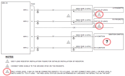
I'm helping a friend with his G3X. The Tachometer suddenly started reading much higher than the actual as well as reading erratically, pegging out and a red X appearing. He was using a tach vent magnetic pickup sensor which had been working fine. Looked at the option of using the 400K resistor to the p-lead but a caution note indicated the GEA-24 must be Mod level 2 and his unit is Mod level 1.

Looking at this diagram it suggests that maybe this doesn't apply when connecting to the ignition switch end. One toggle switch in this case, the other side is electronic ignition.

A T1A9-1 sensor for his slick mag is on order hoping that will fix the problem but looking at other options.
I'm helping a friend with his G3X. The Tachometer suddenly started reading much higher than the actual as well as reading erratically, pegging out and a red X appearing. He was using a tach vent magnetic pickup sensor which had been working fine. Looked at the option of using the 400K resistor to the p-lead but a caution note indicated the GEA-24 must be Mod level 2 and his unit is Mod level 1.

Looking at this diagram it suggests that maybe this doesn't apply when connecting to the ignition switch end. One toggle switch in this case, the other side is electronic ignition.

- Is it possible Mod level 2 does not apply if connected to the ignition switch side?
- What is the path for getting Mod level 2?
A T1A9-1 sensor for his slick mag is on order hoping that will fix the problem but looking at other options.


