What's new
Van's Air Force

Don't miss anything! Register now for full access to the definitive RV support community.

FlyLeds - the Works Kit

Tankerpilot75

Well Known Member
Has anyone installed the Flyleds “Works” kit in on RV with “bat wings” fiberglass tips? I’m thinking about doing this and wondering how well they fit in the 4.5” space the bat wings allow for wing tip lighting and was it a difficult process? How well do you like these lights?

I currently have older led landing lights but they are installed inside the wing tips due to lack of space the bat wings have on their tips .The Whelen strobe and position lights currently installed block a lot of the led landing lights illumination from projecting forward. Tried move the current landing lights where you normally see landing lights in the tips but there just wasn’t enough space under the lens. Became a three day exercise in frustration!

Who is the American distributor?
 
I used them for the non-bat wing tips on my RV-8 project. Blake or Paul are the two guys to talk to.

I built my own and only made one deviation from the instructions. I fit the Circuit Boards to the wing tip before doing any soldering.
 
How hard is it to solder the circuit boards? I’m really not good at that type of work.

I am retired. Was a ham radio nut before college and built lots of "Heathkit" stuff including a TV. At one point while I was working, I was NASA certified for some space flight soldering. I found the FlyLeds to be very simple but I have been soldering longer than I have been flying. (Approaching 41-years since I got my private pilot license.) My temperature controlled soldering station is older than the time I have been a pilot. Easy for me may be moderate difficult for someone else.
 
Has anyone installed the Flyleds “Works” kit in on RV with “bat wings” fiberglass tips? I’m thinking about doing this and wondering how well they fit in the 4.5” space the bat wings allow for wing tip lighting and was it a difficult process? How well do you like these lights?

I currently have older led landing lights but they are installed inside the wing tips due to lack of space the bat wings have on their tips .The Whelen strobe and position lights currently installed block a lot of the led landing lights illumination from projecting forward. Tried move the current landing lights where you normally see landing lights in the tips but there just wasn’t enough space under the lens. Became a three day exercise in frustration!

Who is the American distributor?
Well Jim,
I have not installed the FlyLEDs in a batwing but I have installed in 2 separate airplane’s wingtips. As for performance, they are very bright. If they fit in your wingtips you will like them. I particularly like the capability to light up all around your airplane using the strobes during taxi.
 
I recently installed “The Works” in my buddy’s -9a. They were actually pretty fun to solder together! I’m no soldering expert, I have an Amazon soldering station with a control knob that goes from 1 to 4. I use about 3 or less on most of the connections. They supply nice solder to use, no need to buy anything besides the iron. No flux or special skills.. I did use flush cutters to clip off the tails from the resistors after they are installed. make sure you read the instructions before soldering, as it’s easy to solder a component in the wrong place, but hard to remove it.

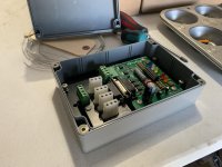
I used a project box to contain the controller board, and screws/nuts with plastic standoffs instead of the snap standoffs provided.

They are super bright!
 

Attachments

  • 64FC25E8-67E0-4CBD-9AAC-E1BEEEC922C0.jpg
    64FC25E8-67E0-4CBD-9AAC-E1BEEEC922C0.jpg
    250.1 KB · Views: 107
  • 47888CF8-2E58-4E0F-B6CA-AB97F829CAA4.jpg
    47888CF8-2E58-4E0F-B6CA-AB97F829CAA4.jpg
    241.8 KB · Views: 108
I used a project box to contain the controller board, and screws/nuts with plastic standoffs instead of the snap standoffs provided.

They are super bright!

A few questions:
1 Where did you source the project box?
2. Where did you place it?
3. Was there an existing strobe system that you replaced? If so how did you address the old system’s previous wiring?
 
Paul’s instruction sheets, along with component identifications, make the assembly so easy that even a caveman can do it. A fun project for someone like me that never did any electronic work before. I also bought a cheaper China built solder station and am happy with its performance. I use it often doing some of the avionics wiring.
 
A few questions:
1 Where did you source the project box?
2. Where did you place it?
3. Was there an existing strobe system that you replaced? If so how did you address the old system’s previous wiring?

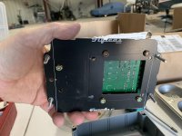
I replaced the whelan strobe box and used the FlyLED whelan adapter board. I didn’t want it to be all exposed back there so a local electronics store and I picked a project box that seemed to work. I still had to modify the corners of the adapter plate to fit, and drill mounting holes though the box. Then I used some plastic standoffs from the electronic store. I also wanted to change the “friction fit” of the whelan board to controller board plug, so I moved the threads of the plug to the other side and sourced longer 4-40 screws to hold it more securely.
As for the wiring, Pauls instructions show you how to reuse it. That was pretty sweet. His instructions are pretty straightforward, and they are on his website if you wanted to pre read them.
 
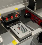
A while back someone posted a 3D print file for a control board box that fit perfect. I’m mounting behind the panel
 

Attachments

  • A1BB9F92-E358-4A43-8972-705705DC7EB4.jpeg
    A1BB9F92-E358-4A43-8972-705705DC7EB4.jpeg
    391.1 KB · Views: 110
Last edited:
How hard is it to solder the circuit boards? I’m really not good at that type of work.

It’s not easy. I screwed it up a few times and it’s still not right. It’s on the bottom of my to-do list. It’s not like drilling out a rivet either. There is very little room for error.

YMMV.
 
It’s not easy. I screwed it up a few times and it’s still not right. It’s on the bottom of my to-do list. It’s not like drilling out a rivet either. There is very little room for error.

YMMV.

I am not an electronics guy.. but I have to say soldering the board was really easy for me.. a fresh solder tip, maybe a couple of YouTube videos could help, but it was super easy and satisfying to have it wick into place! I did it over two hours at the diner table. I used a flat sided solder tip, but most places I just used the sharp corner of it. Probably a pointy solder tip could have made it even easier! After soldering each component, I used a cotton swab with a touch of rubbing alcohol to clean up the look, as the solder seems to have flux core that discolored the area a little. Then I look at the joint with my zoomed in camera.
 
A while back someone posted a 3D print file for a control board box that fit perfect. I’m mounting behind the panel

That is awesome! I saw those for the controller board somewhere, but my setup was the controller board mated with the Whelan adapter board, so it needed to be bigger..
 
I am no expert on soldering but I had no problem with the kit and a lot of fun to put together. My only recommendation is to get a temp control iron with ceramic heater, about $65 on Amazon and keep the tip clean. Keeping the tip clean was the most important part for me. I tried to solder other project with out the temp control station with mixed results, it makes all the difference to me, hard to not get it rite.
 
I made my Works lights while waiting for my wing kit. Super simple. Great instructions. I solder once every 5-10 years. No issues if you follow the tips. Two short evenings of work and I was done. Very happy, and liked doing all the work myself. Like all homebuiling, I learned new things and I'm better for it :)
 
Bit the bullet

This morning I ordered the Flyleds Works kit, the tail light kit, and the strobe power supply adapter kit. Hopefully they’ll fit my batwing tipped RV7A better than my current setup and provide increased illumination. If I’d had current RV7A wingtips with 6.5” vs my 4.5” of available space then I’d probably stayed with the existing system.

Once the Flyleds installation is completed I’ll be selling my older Whelen wingtip and tail strobe/position lights with power supply and two older Aerosport LED landing/taxi lights for a fair price. Anyone interested in this older lighting system please PM me, make a fair offer, and maybe we can do business.
 
Hi Jim,
I assembled the kit you described on my dining room table (some newspaper to protect the table, keep the wife happy)). Absolutely straightforward if you have a decent temperature controlled iron. I did use crimped pins for the d-sub connector instead of the solder pins supplied (my preference).
For ‘bat wing tips’, look at the bare board and how/if it will fit before mounting any parts. You can trim the board some (I used a scotch brite wheel) but don’t cut/grind into the circuit traces, which are difficult to see. The supplied paper templates are useful for this.
 
I just assembled the same kit, with the strobe power supply kit, I don’t think he’ll need that crimp vs soldered connector. The strobe plugs with fit in the adapter board, the existing nav lights go to the boards with screw down plugs.. read the instructions twice before assembling anything, fit the boards to the wings first, keep the Left and right boards laid out separate. I used my cellphone camera to zoom in and see some of the fine details of the + or - on the components.
 
Control Module Box

I'll print you one for a $25 donation to Doug. Obviously I can't do this for everyone but will do on a request and if I have time basis.

A few questions:
1 Where did you source the project box?
2. Where did you place it?
3. Was there an existing strobe system that you replaced? If so how did you address the old system’s previous wiring?
 
Hi Bill
A generous offer, but Jim's setup is a little different and won't work with the 3D print files. His The Works controller board gets mounted on a plate that's the same size as the old Whelen power supplies and it has an adapter board hanging off it.

I am revisiting the design of this again and the circuitry will be able to be covered with a Hammond box.
These power supplies were usually mounted either under a seat or on the wall behind the rear bulkhead, so I figured that no one would want a box as they were locked far away from stray boots and bags. I was wrong!

 
Thanks Paul, I didn't realize they were different. I was referencing the photo on post 12, I can print those.

Hi Bill
A generous offer, but Jim's setup is a little different and won't work with the 3D print files. His The Works controller board gets mounted on a plate that's the same size as the old Whelen power supplies and it has an adapter board hanging off it.

I am revisiting the design of this again and the circuitry will be able to be covered with a Hammond box.
These power supplies were usually mounted either under a seat or on the wall behind the rear bulkhead, so I figured that no one would want a box as they were locked far away from stray boots and bags. I was wrong!

 
One of the yellow “dots” on one of my landing light LED’s came off and now the light emits a bluish tone. Can the dot be glued back on?
 
Hi Ray

As per the email I sent you:
Unfortunately that LED needs to be replaced. Removing the yellow dome also takes the white phosphor layer with it, exposing the blue LED below.
If you send either just the light PCB or the entire light as is back to Flyboy Accessories they will repair the light and return it to you.

 
I’m remiss in not posting a follow up my FlyLeds installation. First, since I wasn’t wild about soldering the boards I had Paul do the soldering. That was money well spent in my opinion.

The installation challenge was of course my bat wingtips. Filing down the boards to fit the space without damaging them was difficult but doable. I had to enlarge the holes in the wingtips to accommodate the electronics leaving very little room to secure the boards to the tips. The use of nut plates was impossible due to limited space and thickness of the fiberglass at the corners. I eventually decided on stainless steel screws, small washers and locking nuts which were extremely challenging to install in the very tight spaces. However everything did eventually fit!

For the control module box, as Paul said, my control board with strobe adapter board was at least as big as my old strobe unit module. After one incorrect plastic box order, I found on Amazon a box that allowed space for everything installed. Using a drill and dremmel, I modified the box to accommodate the controller, fit my old strobe mounting location nut plates, and cut airflow vents for any cooling issues. I used the aircraft’s existing wiring to accommodate the setup. The controller was installed behind the cargo panel where the old strobe module was.

Paul’s written instructions were excellent and he was very responsive to several email questions. Having flown with this lighting system for several months now I can say it was well worth the time and expense. Several folks have commented on the increased daytime visibility of my aircraft with the wigwag lights on. Strobe, position, landing and taxi lights provide truly an amazing amount of illumination.
 
Back
Top