What's new
Van's Air Force

Don't miss anything! Register now for full access to the definitive RV support community.

Dimmer for Strip LEDs Wiring Confusion

rockitdoc

Well Known Member
Sponsor
I have the Perihelion Designs dimmers from Steinair. Got to wiring them today and immediately ran into confusion. The diagram shown has two outputs, one switched and one variable. I have tried every which way to get the dimmer to dim my LEDs with no luck.
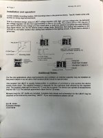
Dimmer Instructions?.jpg

Obviously I am doing something wrong.

Here's how I hooked stuff up:

Dimmer input connected to 14.2v DC
Dimmer ground connected to ship's ground

then two tries to get dimmer to dim as follows:

1.
(-) wire from LED to ship's ground
(+) wire from LED to switched output on dimmer

LED's light up but do not dim


2.
(-) wire from LED to ship's ground
(+) wire from LED to variable output on dimmer

LED's light up but do not dim


What am I missing? I got online as suggested in the instructions but got even more confused.
 
Works fine

(Please don’t tell my plane this won’t work )
Assuming 12V system and LED(S) designed for +12V

Ground -> aircraft ground

Switched output -> +12V output to another dimmer or ???

Variable output -> to +12V input of LED

Input -> +12V input from plane

Regards,
 
(Please don’t tell my plane this won’t work )
Assuming 12V system and LED(S) designed for +12V

Ground -> aircraft ground

Switched output -> +12V output to another dimmer or ???

Variable output -> to +12V input of LED

Input -> +12V input from plane

Regards,

Roy,

That's how I wired it during experimenting. Switched output not connected, Variable connected to (+) LED, (-) LED to ground, +12v from bus to Input.

It lights up, but does not dim.

The lit from Steinair/Perihelion says go to the net and look at wiring for LM317 devices (which is what the Steinair thingy is). This is what you find:

https://www.circuits-diy.com/led-driver-circuit-using-lm317-voltage-regulator/

Looks like a resistor is needed between the variable and fixed outputs?

Flummoxed, again.....
 
Last edited:
I’m very sorry. My fault for commenting on something I didn’t have specific experience with.
Mike
 
These are what I got:

https://www.steinair.com/product/led-strip-light-red-3ft/

Doesn't say whether dimmable or not. I'll have to call to find out, but it seems odd Stein would sell non-dimmable LEDs when they sell the dimmer switch, but, hey, could be.

I'll let everybody know what I find out.

I am fairly certain this is same thing I have in my plane.. and it's useless for night flying.. I tried.. I have it on some dimmer and lowest it goes is still way way too bright... I tried using it once and gave up after 20-30 seconds of playing with it..

PS I did not install this (previous owner did) so I can't confirm right now if this is identical product but looks the same to me..
 
Strip LED

These are what I got:

https://www.steinair.com/product/led-strip-light-red-3ft/

Doesn't say whether dimmable or not. I'll have to call to find out, but it seems odd Stein would sell non-dimmable LEDs when they sell the dimmer switch, but, hey, could be.

I'll let everybody know what I find out.

Same here. Red and white and two of the dimmers.
I agree. Why sell a product if it's not compatible with the dimmer. Let us know.
 
Dimming LEDs

I suspect what you are doing is trying to ground the LED to the dimmer without grounding the dimmer. It also could be that you are hooking the LED up backwards. LEDs require the correct polarity to conduct and will not work if the polarity is reversed.

Try looping a ground wire from the neg LED to the GRnd on the dimmer to a Grnd on the buss.

FYI, A little primer on how LEDs work.

First, they conduct only in one direction. Polarity has to be correct.

Second, they all have a 'forward voltage' below which they do not conduct at all. Once they reach the forward voltage they light up.

Caution, before you hook them up to a current source:

Third, LEDs do not self limit the current. So if not limited by a resistor or pulse modulator they will quickly self destruct.

Forth, the light production of LEDs is not linier with voltage. For this reason an LED mated with a variable resistor will not have a linier response, but will be sensitive in the lower voltages and somewhat flat in the higher voltages. This is why variable pulse width modulator type LED controllers are preferred for high end applications

An example:

Lets say you have an LED the has a 2.0V forward voltage. It will light with any voltage above 2V. However unless the current is limited to the rated current it will burn up.

Lets say I put 4 in series, 4X2 = 8 volts to light up. But again without current limiting it will burn up one or more in an instant.

Lets say I have a big LED that is rated for up to 2 amps. All I need to do is provide a resistor that limits the current to 2 amps at the somewhere above the forward voltage of the LED, using Ohms law R=E/I
R= Resistor stated in Ohms
E= the required current drop (so in the above single LED case with a 14V buss and 2V LED, the current drop would need to be 12V)
I = current desired in this case up to 2 amps.

R = 12/2 = 6 ohms

To size for the wattage dumped as heat in the resistor use the formula
W = E*I

W= wattage rating of the resistor
E = Current drop
I = current flow

W = 12*2 = 24 watts rating for a 6 ohm resistor.

Now if you want to dim add a variable resistor to adjust the circuit for dimming.
 
So, a little troubleshooting this morning.

The switched output pole on the dimmer gives 14.2 vDC no matter where the pot is turned. The variable output pole gives 12.2 vDC no matter where the pot is turned, high to low. So, at least the two outputs are different! But, they don't yield different voltages from high to low, so no wonder the LEDs don't dim.

So, I must still be doing something wrong, or I was mislead into thinking this device was a plug and play dimmer. I am not opposed to adding some kind of doodad into the circuit to get this thing to work, but if that is necessary, it would have been good to know this before going through all these gyrations. Also, I was hoping a graduate degree in electrical engineering wasn't going to be necessary to hook this thing up, although the previous post got me a lot closer to that achievement. Thank you! It seems there might be hope to dimmer panel lights. BTW, I did ground the dimmer and the LEDs to ship ground as suggested by the previous post in this endeavor. Oh, and they are lighting up, so polarity must be right, right?
 
Last edited:
So, a little troubleshooting this morning.

The switched output pole on the dimmer gives 14.2 vDC no matter where the pot is turned. The variable output pole gives 12.2 vDC no matter where the pot is turned, high to low. So, at least the two outputs are different! But, they don't yield different voltages from high to low, so no wonder the LEDs don't dim.

So, I must still be doing something wrong, or I was mislead into thinking this device was a plug and play dimmer. I am not opposed to adding some kind of doodad into the circuit to get this thing to work, but if that is necessary, it would have been good to know this before going through all these gyrations. Also, I was hoping a graduate degree in electrical engineering wasn't going to be necessary to hook this thing up, although the previous post got me a lot closer to that achievement. Thank you! It seems there might be hope to dimmer panel lights. BTW, I did ground the dimmer and the LEDs to ship ground as suggested by the previous post in this endeavor. Oh, and they are lighting up, so polarity must be right, right?

Dimmer is likely defective. I have used quite a few LM317 based voltage regulators and they should provide variable voltage when tested on the bench. They are pretty simple chips, using pretty simple circuits. So, to get the results above, something on the board must be defective or a trace is shorted or open. Look at the instructions about Vout limiting. Possible someone cut the trace, but didn't install a resistor. See stuff like this when a retailer accepts returns, but doesn't check the product.
 
Last edited:
I have used several of these devices over the years for various dimmers. For me they have worked well with no fancy stuff required. Just hooked the variable output to the input of a 12v LED string. Even worked well with a 4 colour LED string (White/Red/Blue/Green) with the colour selected by a rotary switch - not much practical use but looked cool!

If the variable output isnt variable between 12v to 5v then it doesn't work correctly, ask Stein to replace.
Pete
 
Dimmer is likely defective. I have used quite a few LM317 based voltage regulators and they should provide variable voltage when tested on the bench. They are pretty simple chips, using pretty simple circuits. So, to get the results above, something on the board must be defective or a trace is shorted or open. Look at the instructions about Vout limiting. Possible someone cut the trace, but didn't install a resistor. See stuff like this when a retailer accepts returns, but doesn't check the product.
I have two. Both behave same way. Both defective? Could be if it was a production run issue.
 
I have two. Both behave same way. Both defective? Could be if it was a production run issue.

Go grab a data sheet for the LM317 off the web. Look at the sample schematic for a constant voltage regulator (just the 317, a couple capacitors and two resistors, one being a rheostat in this case). Then test with your meter. These are dead simple circuits - no graduate degree required. Yes, a bad run can easily allow excess solder to bridge surface mount chips. Most large companies that uses flow solder machines will test every board, as this kind of stuff happens. They also usually do a 50C test to get the board to grow and see what stops working due to a cold solder joint.
 
Last edited:
Go grab a data sheet for the LM317 off the web. Look at the sample schematic for a constant voltage regulator (just the 317, a couple capacitors and two resistors, one being a rheostat in this case). Then test with your meter. These are dead simple circuits - no graduate degree required. Yes, a bad run can easily allow excess solder to bridge surface mount chips. Most large companies that uses flow solder machines will test every board, as this kind of stuff happens. They also usually do a 50C test to get the board to grow and see what stops working due to a cold solder joint.

I went to the web and looked at the LM317 diagrams. Didn't help me much. The LM317's have three poles labelled 'in', 'out', and 'adjust'. The Stein device has four: 'input', 'switched out', 'variable out' and 'ground'. The web diagrams have a variable resistor wired to the 'out'. I assume this is the potentiometer on the Stein device, but I dunno. My hope is both of my Steins are defective. Calls to Stein this morning have resulted in no contact. I have already spent more time on this than should be necessary. Ugh.
 
I also have that same dimmer, and the red light strip - both purchased from Stein, and it works great. The variable output goes to the light strip and dims the light strip down to a very low level. I have another wire connect to the switched output for another device I want to be lit, and that one doesn’t dim. You may have a faulty dimmer(s).
 
I also have that same dimmer, and the red light strip - both purchased from Stein, and it works great. The variable output goes to the light strip and dims the light strip down to a very low level. I have another wire connect to the switched output for another device I want to be lit, and that one doesn’t dim. You may have a faulty dimmer(s).

Stein contacted me this am and described the wiring you provided above. I wired it this way and get no dimming. Gotta be a bad dimmer.
 
It is unlikely that your dimmer is defective. LED brightness is controlled by
current, not voltage. Voltage measurements are not very useful in this
application. Below is a circuit for dimming LEDs. Notice that each LED has a
resistor in series. Adding a series resistor to each of your LEDs will likely solve
the problem. Choosing the resistor value is trial and error. Perhaps Stein can
help with that.
-
 

Attachments

  • LED Dimmer.png
    LED Dimmer.png
    18.8 KB · Views: 45
Success with First Wired Stuff

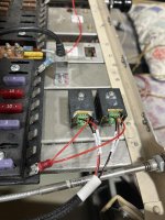
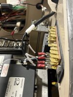
Success! Wired up the dimmers and bench tested the connections. It works! Thanks for all the help everybody. Here's what the wiring at the dimmers and grounds look like.
Scott

Panel Lites Dimmer Wired.jpg

Panel Lites Grounds.jpg

Everything needs to get mounted, but the wires reach and fit.
 
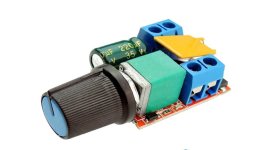
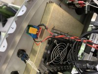
I just put a dimmer in my new build to drive an LED light strip. This was obtained from a popular on-line site.

It works as advertised, but because my light strip was blindingly bright, I put a 150 ohm resistor in series (either leg will work). That helps reduced the minimum brightness for night ops. It also has a power switch to turn the lamp off.

For the tekkies: Uses an LM555 timer chip, 78L05 voltage regulator, a power transistor and a PTC fuse. Normal operation up to 15V, peak 35V. Should be 'good enough'. All 1970's technology.

I could have built one, but for $7 (for two), it's a great deal.

IMG_0025.jpeg

IMG_3289.jpg

IMG_3291.jpg
 
Last edited:
because my light strip was blindingly bright, I put a 150 ohm resistor in series (either leg will work). That helps reduced the minimum brightness for night ops. It also has a power switch to turn the lamp off.

Does this tick work for the 12v fed strips that have the resistors built in. I used the low output strip, but still wouldn't mind the ability to have a bit less light and never use full power on it. I dont have a fancy dimmer, just a rheostat wired as a voltage divider.
 
Back
Top