What's new
Van's Air Force

Don't miss anything! Register now for full access to the definitive RV support community.

DeltaHawk for RV-14

Craig,

Thanks for the updates on this and please keep them coming, great work you’re all doing there.

I’m new to homebuilding having just started my RV-10 tailcone, but not to product development. It’s one thing to develop great technology but another to be commercially successful with it. You can have the best solution for any given challenge, but if market conditions are against you it can be almost impossible to build a business around it. Until those conditions change or you find a better application. If engine manufacturers are able to utilize decades-old machinery to make proven engines at low cost but can sell them for high prices, that’s hard to compete with. Until fuel options change, for example. Disruption is hard, but it’s amazing when it happens. Before it happens, most people think it is impossible. When it does, most people say it was inevitable. It never was and it never is—it takes relentless developers to keep pushing and bridge the gap.

Kudos to you and the team and I wish you best of luck. By the time I get to my FWF kit, I look forward to having another engine option to choose from.
I think the fuel options may end up being the market disruption needed (especially in California). 100UL vs 100LL cost and availability will be, in my opinion, a big factor in the success of this engine. Keeping my fingers crossed that they succeed!
 
I think the fuel options may end up being the market disruption needed (especially in California). 100UL vs 100LL cost and availability will be, in my opinion, a big factor in the success of this engine. Keeping my fingers crossed that they succeed!
Me too but I’ve been waiting the better part of two decades…
 
All,

A few more things to share. See below the CADs on what should be the final design and layout of the ducting as well as the cowl design. DeltaHawk is certainly letting function drive form as the performance of the package is paramount. However, I think they've done a great job maintaining the aesthetic of the RV14, while allowing for the distinct design elements that differentiate the DeltaHawk powered RV14 from one with a Lycoming. As beauty is in the eye of the beholder - let us know what you think. Incidentally, as folks will likely spot these, let me point out a few differences between the stock RV and the DH in regards to the FF:

> Yes, the cowling is longer. By about 3". As I posted earlier in this thread, its almost identicle to the cowling length on my current RV14. Hopefully this will give some perspective on how 'long' the nose will be. My 2-cents, it will not be very noticable, and likely only to those who are very familiar with the stock RV14. I'll post more detail on the exact structure of the cowling as we get it fitted in place.

> The nose cone/spinner are larger than the stock RV14. I cannot speak to this (aestheticly) as I have the stock ones on my current14. But, from looking at the CAD's, it appears it will look fine.

> There is an inlet on the lower cowl. This is similar to what I currently have on my 14, and also somewhat like is seen on a lot of RV7's. The shape of the DeltaHawk inlet is unique and will likely be the most noticable clue that to whats under the hood.


Fabrication is moving forward and, as I mentioned previously, DH will have the entire set-up (FF package with engine) mated to the fuselage to show at Air Venture this year before sending it on the Eugene for final assembly (of the airframe) and initial flight testing. The caveat here is that until static testing is completed, the design is still subject to modifications. Much work has been done to ensure everything plays well together - but, as builders are all too aware of, nothing quite duplicates the real world. That said, DeltaHawk's experience gained with the Cirrus and other installations is proving to be a great benefit to the RV14 project.

Finally, I will have something to share on the panel later this week.

Craig
 

Attachments

  • DH RV14 ducting.png
    DH RV14 ducting.png
    1.4 MB · Views: 162
  • cowling DH RV14.png
    cowling DH RV14.png
    741.7 KB · Views: 153
  • DH RV14 airframe.png
    DH RV14 airframe.png
    236.4 KB · Views: 153
Last edited:
Craig,

How will you make the transition from the cowl inlets to the duct? I’d guess neoprene sleeves like on the James cowl and plenum.

When you say the spinner is larger is that length, diameter or both? Like the RV-10 the 14 could use a larger diameter spinner. I’m using a 14” on the new RV-10 project.

Carl
 
Carl,
Re nose cone/spinner - A bit bigger all around. As for the cowling - as we get into the smaller details, the chances of something being modified increases until the final design is fitted. So I can’t speak to the transition yet. Nonetheless, DH should have all this worked out by the Air Venture and on display for all to see.
Craig
 
A few more things to share. See below the CADs on what should be the final design and layout of the ducting as well as the cowl design. DeltaHawk is certainly letting function drive form as the performance of the package is paramount. However, I think they've done a great job maintaining the aesthetic of the RV14, while allowing for the distinct design elements that differentiate the DeltaHawk powered RV14 from one with a Lycoming. As beauty is in the eye of the beholder - let us know what you think.
Hi Craig, thanks for sharing the pics of the updated cowl and ductwork. Overall it's looking pretty good but one thing that jumps out to me is the break in the plane between the forward upper fuselage skin and the top surface of the cowl where they meet at the firewall. On the original RV-14, Van's lofted the upper surface lines to flow nicely together in the same plane. This is one of those things that won't bother some folks, but people like me who are cursed with an eye for this sort of detail will notice the disparity immediately and it will be much more obvious on a completed airplane with glossy paint.

Looking back at the pics in your 4/18/24 post, I don't see any structure (engine, mount, etc) that is up high enough to prevent lowering the upper cowl surface to be in the same plane as the forward fuselage skin, so I hope DH will consider making that change to improve the aesthetics. The larger spinner will require the cowl 'fairing' area behind it to extend further aft before it blends/disappears into the upper surface, but IMO that would look better than how it is currently lofted.

Will DH be making a custom spinner or leaving that to prop manufacturers? For ideal aesthetics and aerodynamics, the lines of the spinner and cowl should match nicely...Van's has accomplished that by designing & providing both. Hoping there will be a matching carbon fiber spinner available.

The cooling inlets in the pictures look like they have a sharp edge, this might just be a preliminary drawing but in the final iteration there should be a generous radius around the inboard edges of the inlets (lots of NACA research to support this and you can also see it in how Van's designed the original -14 cowl inlets).

Also, the top view drawing you provided does not appear to have any engine offset. The RV-14, like most low wing airplanes, was designed with the engine angled several degrees nose right to help reduce the amount of nose right rudder/trim needed due to P-factor. Obviously this mounting angle affects the engine mount, forward cowl shape, and possibly the fit of the ducting as well. Curious why DH doesn't appear to be implementing any offset into the design for the -14?

Thanks,
 

Attachments

  • DH cowl loft lines.png
    DH cowl loft lines.png
    453.5 KB · Views: 77
Last edited:
Mark,

Thanks for the comments, and the detailed drawing. I reached out to DeltaHawk so I could better respond to your questions/comments. I'll address them in the order you mentioned them.

Regarding the top surface of the cowling and how it intersects with the fuselage: DeltaHawk says their design is driven partially to accommodate the flywheel of the engine (see pic below). That said, their experience is that the break in the plane (relative to the fuse) is more noticeable in CAD renderings than it will be in real life. Additonally, the top of the outersides of the cowling (left and right outboard sides) will be almost exactly in line with the plane of the fuse - its only as one moves closer to the center portion of the cowling, the angle of the plane diverges a bit from the plane of the fuse (to accomodate the flywheel).

The Spinner: Both the Cowling and the Spinner are carbon fiber and purpose built for the DeltaHawk application. It will be part of the FF kit and supplied by DeltaHawk.

Additionally, and in anticipaction of someone asking about this, the cowl will be comprised of 4 pieces: the Upper, the Lower, and two pieces directly behind the spinner. I am ecstatic about this as it should side-step one of my pet peeves' with the Van's cowl (or with my own abilities to deal with it!) - that is the gymnastics required to remove the lower cowling without scraping it up against the prop or spinner. I don't know if removing the lower cowl is a big issue on the 14A, but its a pain to do on the taildragger. DeltaHawk is also putting an Oil Drain Door in the lower panel, so oil changes can be accomplished without removing the lower cowling. And, remember, there are no spark plugs to change - so, yet another reason removing the lower cowl should be a less frequent chore.

The Cooling Inlets (in the cowl): DeltaHawk say the inlets were designed using NACA profiles and they have done extensive modeling to optimize the expected airflow conditions. Again, the CAD drawings were just to show a rough sketch of what the design will look like. Also, the inlet ducting will be sleeved to the inlet cowl.

The Off-Set of the Engine: DeltaHawk says that according to Vans, the RV14 (stock) does not have an offset. But, Generally, the off-sets for planes of this size and power combination would be less than 1 degree. That said, if flight testing indicated the DH RV14 would benefit from a bit of off-set, it would be easy enough to shim the mount (and, then build later mounts to reflect this).

I hope I've addressed your comments well enough. Its clear there are a number or VAF members with useful knowledge and experience, and we appreciate the extra eyeballs and feedback.

Craig
 

Attachments

  • cowl 4.29.24.png
    cowl 4.29.24.png
    460.1 KB · Views: 86
Mark,

Thanks for the comments, and the detailed drawing. I reached out to DeltaHawk so I could better respond to your questions/comments. I'll address them in the order you mentioned them.

Regarding the top surface of the cowling and how it intersects with the fuselage: DeltaHawk says their design is driven partially to accommodate the flywheel of the engine (see pic below). That said, their experience is that the break in the plane (relative to the fuse) is more noticeable in CAD renderings than it will be in real life. Additonally, the top of the outersides of the cowling (left and right outboard sides) will be almost exactly in line with the plane of the fuse - its only as one moves closer to the center portion of the cowling, the angle of the plane diverges a bit from the plane of the fuse (to accomodate the flywheel).

The Spinner: Both the Cowling and the Spinner are carbon fiber and purpose built for the DeltaHawk application. It will be part of the FF kit and supplied by DeltaHawk.

Additionally, and in anticipaction of someone asking about this, the cowl will be comprised of 4 pieces: the Upper, the Lower, and two pieces directly behind the spinner. I am ecstatic about this as it should side-step one of my pet peeves' with the Van's cowl (or with my own abilities to deal with it!) - that is the gymnastics required to remove the lower cowling without scraping it up against the prop or spinner. I don't know if removing the lower cowl is a big issue on the 14A, but its a pain to do on the taildragger. DeltaHawk is also putting an Oil Drain Door in the lower panel, so oil changes can be accomplished without removing the lower cowling. And, remember, there are no spark plugs to change - so, yet another reason removing the lower cowl should be a less frequent chore.

The Cooling Inlets (in the cowl): DeltaHawk say the inlets were designed using NACA profiles and they have done extensive modeling to optimize the expected airflow conditions. Again, the CAD drawings were just to show a rough sketch of what the design will look like. Also, the inlet ducting will be sleeved to the inlet cowl.

The Off-Set of the Engine: DeltaHawk says that according to Vans, the RV14 (stock) does not have an offset. But, Generally, the off-sets for planes of this size and power combination would be less than 1 degree. That said, if flight testing indicated the DH RV14 would benefit from a bit of off-set, it would be easy enough to shim the mount (and, then build later mounts to reflect this).

I hope I've addressed your comments well enough. Its clear there are a number or VAF members with useful knowledge and experience, and we appreciate the extra eyeballs and feedback.

Craig
Ok thanks, I'll reserve judgement on the aesthetics for the final product when the airplane is finished ;). As for the 4 piece cowl, agree that should make removal/installation easier around the prop/spinner area, although the tradeoff will be increased fastener count to remove/reinstall. And the more parts & mating surfaces, the harder it is to get a nice fit all around...but with modern CAD/CNC tools used to make the molds directly and the stiffness of carbon fiber, the parts should fit very well 🤞.

Regarding engine thrustline offset, interesting that Van's says there isn't any on the -14. I don't have my finish kit yet...I know my -8 had it and assumed all RV's were that way. You can clearly see the offset on the spinner in Van's 3-view drawing of the RV-14, but perhaps that was only used for the prototype and removed for the production kits. One note, you can't just add shims to the mount to produce an offset thrustline (unless you don't mind swinging the entire prop/spinner to the right of fuselage centerline). All low wing aircraft I have looked at that have the thrustline offset to the right do so by keeping the front of the crankshaft on the centerline of the fuselage and moving the back of the engine to the left of centerline. But anyway, if the stock -14 doesn't need offset thrustline, the DH powered one probably won't either.
 

Attachments

  • RV-14 engine offset.png
    RV-14 engine offset.png
    18.1 KB · Views: 9
Last edited:
Ok thanks, I'll reserve judgement on the aesthetics for the final product when the airplane is finished ;). As for the 4 piece cowl, agree that should make removal/installation easier around the prop/spinner area, although the tradeoff will be increased fastener count to remove/reinstall. And the more parts & mating surfaces, the harder it is to get a nice fit all around...but with modern CAD/CNC tools used to make the molds directly and the stiffness of carbon fiber, the parts should fit very well 🤞.

Regarding engine thrustline offset, interesting that Van's says there isn't any on the -14. I don't have my finish kit yet...I know my -8 had it and assumed all RV's were that way. You can clearly see the offset on the spinner in Van's 3-view drawing of the RV-14, but perhaps that was only used for the prototype and removed for the production kits. One note, you can't just add shims to the mount to produce an offset thrustline (unless you don't mind swinging the entire prop/spinner to the right of fuselage centerline). All low wing aircraft I have looked at that have the thrustline offset to the right do so by keeping the front of the crankshaft on the centerline of the fuselage and moving the back of the engine to the left of centerline. But anyway, if the stock -14 doesn't need offset thrustline, the DH powered one probably won't either.
Hi All,

Just a word on offset. There is a noticeable amount of right thrust in the stock Lycoming setup. The aft side of the engine is offset left in order to achieve this right thrust line while maintaining a centered prop shaft at the forward edge. Please consider double checking this.

I love your progress!

-George
 
All,

Regarding the off-set (and, a few other things):

I have gone back to DeltaHawk to confirm their understanding that the RV14 does not have off-set. They are quite certain that was what they were told from their contact at Van’s.

That said, the project is at the point where the mount is fabricated and lots of other things are well along, too. Its felt getting the plane finished and flying is likely the best strategy to further evaluate the overall design and performance of the engine package.

On that point, one of the primary goals of the flight testing is to determine what must be tweaked to finalize the whole package for general consumption. Possibly, that will include adjusting the off-set, or who knows what else. An area being given particular attention is the effectiveness and efficiency of the cooling systems - much work went into their design, but as most folks know these systems are notoriously complicated in real life vs on paper/computer.

Unfortunately, there is not sufficient time to complete the plane and test fly it before Air Venture - but, as I mentioned before, DeltaHawk plans to have the FF package mounted to our fuselage on display there. After that, work will continue at Synergy Air (Eugene) to complete the final assembly and flight testing.

Also, related to all this is that DeltaHawk is currently in development of the next iteration of the block used in the DHK180/200/235 engines. Based on the data/experience gathered to date and from the use of the engine in the current (flying) test-beds (Cirrus, Cessna, etc), DeltaHawk refined the design of the block. Two of the many outcomes of this exercise are a weight savings of about 10-12 pounds and a slightly smaller diameter flywheel. Neither were primary goals of this process, but both will be of value in the application of the engine on the RV models (I think this is an example of 'serendipity'!). The new block will require modifications to the mount that was built for our current test plane, and will allow for some tweaking of the cowling design (to even closer replicate the original Vans design). It may be more apparent now why DeltaHawk is anxious to get our current plane up and flying so they can move forward with a final version with the new, lighter block (200 hp model). And, additionally, a very refined FF package that folks can order.

Lastly, DeltaHawk wanted me to convey their sincere appreciation for the interest in the project and the feedback from the forum. They are listening and learning from the collective knowledge and experience of the forum's members.

Craig
 
Something else to share…

Here is the panel we will be using in the DeltaHawk RV14. There's a lot to unpack here, so look at the schematic and the panel rendering first and then the comments below should mostly make sense. Hopefully, I did this correctly and the pics have enough resolution - I was able to zoom in on features after posting.

DH RV14 Panel A.1a.JPG

DH RV14 a.2.png


Back Ground: The panel for the DeltaHawk project was originally built about two years ago by Aerotronics (Jason Smith’s outfit in Billings, Mt). He's done countless panels for Synergy Air in Eugene for RV builders - and, is almost exclusively used by the RV14 builders there. The panel was originally intended to be in my 'next' RV14 - which fortuitously became the test plane for DeltaHawk. The original design was a new iteration of the panel in my current RV14, with some minor modifications to allow a co-pilot to have more access/control over the avionics. The biggest change vs the old panel was the addition of a 7” G3X on the co-pilot side. Now, with the introduction of the DeltaHawk engine to the mix, there are a few more alterations.

Features - In General:

Sharp eyes may notice the additional real estate on the DeltaHawk panel vs a stock RV14 panel. It comes from two (2) sub-panels - to the left and right of the throttle area. Both lightly recessed (towards the firewall about an inch). This idea came from an RV7 built around 2000 by Mitchell Lock – long before he joined Van's and became their CEO (I purchased this RV from Mitch in 2003 and accumulated about 1000 hours on it before selling). I never found the lower panels to hamper clearance for my legs (I’m just shy of 6' tall), and the added real estate opened layout options for the upper panels. On the DeltaHawk panel most of the switches are located on the lower panels. There are also some circuit breakers - but most of the circuitry is routed through the VP-X electronic circuit breaker system (it didn’t have the capacity for all of the circuits in this panel).

The Panel is set up to allow two (2) pilots to share tasks, although it will function for a solo pilot just fine.

Avionics:

Full IFR Garmin Set-up:

GTN 750i

G3X (10” and 7")

Remote Audio panel, Remote Transponder, Remote Comm2 - all accessible thru the G3Xs (IMO the G3X interface is superior to the head mount for these items, and it frees up significant space on the panel for the TVs).

Auto-Pilot

Connexts - for bluetooth streaming

Additionally, the DH panel has two layers of redundancy. First, dual G3Xs allow for reversionary mode should one unit fail (much like having a G5). Secondly, there is accommodation for a Stratus/Sentry and iPad(s) running Foreflight. Should the whole panel go dark (unlikely, but one never knows) - one could navigate or manually shoot an emergency approach using the ADHRS generated from the Stratus/Sentry and displayed on the iPad. The iPad and the Stratus/Sentry have dedicated USB charging ports, but also have internal batteries so they will continue to operate for quite some time in the event of a power loss.

Specifics on the various sections of the panel:

Lower Panels:

No Mixture Control Knob
. The DeltaHawk engine doesn't use one. It has only Throttle and Prop Controls.

Switches: Laid out generally in order of use (left to right). I will only cover the ones that may need some 'splainin'.

“EFIS” switch: Located to the far left since, with the Garmin, its good to power up the G3X asap, as all the engine gauges are displayed via its MFD. One would want this up and running before engine start and it takes about 30 seconds to power up.

Start" switch: Replaces the Keyed Ignition one sees in most Lycoming installations. Hold the switch 'down' to heat up the glow plug, then hold the switch 'up' to start the engine.

“Idle Gov” switch: This is particular to the DeltaHawk engine as compression ignition engines are difficult to control at idle. The Idle Governor works in conjunction with the fuel control unit. The idle governor, when turned on, will ensure the engine never operates below 1200 rpm. This needs to be on a pilot operated switch to shutdown the engine. (*simplified* shutdown procedures are to turn off idle gov and bring power lever to idle).

Fuel Pump” switch: This is located on the right sub-panel, a bit out of the way – as its there primarily as a back-up to the mechanically driven fuel pumps on the engine. The delivery fuel pump sends fuel from tanks at about ~50 psi to the high-pressure fuel pump. The high-pressure fuel pump sends the fuel at very high pressures to each injector. The electrical pump is a backup for the delivery fuel pump and is an FAA part 33 requirement. DH is still developing the fuel system procedures; typically, the boost pump is activated during start-up, then turned “off” at commencement taxi, and then remains in the 'off' state. The G3X is configured to indicate low fuel pressure. If this were to happen the boost pump should be turned “On”.

Emergency Engine Stop Control (pull cable): Required to allow for two (2) methods of shutdown. Typical shutdown is completed by switching “off” the Idle Gov and bringing the power lever to “idle”. Since this is a compression ignition engine, the secondary method of shutdown is to pull the Emergency Engine Stop. This cable will close off induction air, quickly shutting down the engine.

Left Upper Panel
:

iPhone: The schematic doesn’t show the details well, but we have an iPhone (on an articulating mount) to the left of the G3X. Again, personal preference. Having put the iphone in about every conceivable place in the RV7 and the RV14, this seems to be one of the best options for readability and accessibility. A USB outlet is adjacent to the mount, for charging the phone flight. Personally, I tend to use the full-sized iPad (on the right side of the panel) for navigation and other stuff, but its also handy to have the iPhone to access checklists (foreflight), checking weather along a route, and managing playlists (bluetoothed through the panel).

Cabin Heat: Heat is NOT supplied via a heat muff on the exhaust, instead it taps into heat from the coolant hoses. The heat system is located aft of the firewall. (other than the coolant lines that supply hot coolant to the heat exchanger) and sits against the firewall above the exhaust tunnel

The Cabin heat control cable controls the flow of coolant through the firewall. With it pulled, Coolant will flow through the cabin heat exchanger. (wouldn’t want a 200F heat exchanger sitting in the cabin on a hot day. There are air diverters/ducting to direct the heat towards pilot/copilot feet.

The control knob controls the speed of the fan we are using to recirculate the air through the heat exchanger. This system eliminates the risk of CO and the need for the cabin heat doors.

Warning Lights: Probably all are self-explanatory except the "Idle Gov". This is to warn the pilot the Idle Gov is not engaged (once the engine warms up, it should be engaged for the entire flight). Idle Gov light will illuminate if the Idle Governor is not receiving power.


Center Upper Panel:

Overall, this area doesn't need much commentary. While the Comm2, Transponder, and Audio panel are all remote mounted (accessed thru the G3X), our preference is to have the actual panel head for the Auto-Pilot. Personally, I use the AP in probably 80% of my flying. Even when not in IMC, the AP is being used to hold altitude, climb/descend, steer with the heading knob, or follow a route in a flight plan. Hand-flying the plane is great, but on many flights its very enjoyable to set the AP, listen to some great music, and enjoy the amazing scenery! Having the AP head below the GTN works nicely as it enables easy back-and-forth with the Throttle/Mixture controls.

Right Upper Panel:

Mostly self-explanatory again. The dark matter on the right represents a full-sized iPad. It doesn't show that well on the schematic – especially in that with the mount we use, the iPad can be positioned in almost limitless orientations. I currently have this set-up in my RV14. It uses a MyGoFlight articulating mount - the iPad can be flat against the panel, rotated, tilted, or even extended over towards the pilot (useful when flying solo and one doesn’t want to strain to see/reach the iPad). A USB plug for in-flight charging is located next to the mount (behind the iPad). Also, behind the iPad is a glove box.

Astute observers who have not fallen asleep from my long-windedness, will note there are leading edge light controls above the 7" G3X and may wonder why these are necessary when the lighting switches on the lower left panel seem to cover all the bases. It’s for more lighting - especially when landing on a grass strip in the middle of Nowhere Mountains. The Aveo Zip tips are nice, but they lack a bit of forward lighting for this type of venue. So, we're wired up for an off-road set-up, but have yet to decide on which brand of lights use. Looking for something like "Elk Spotters 1000". We’ll be visiting all the light guys at Air Venture this year.

Few Random things:

Inogen Oxygen System
. We will likely be using Windblade's Inogen O2 concentrator. I use this in my current 14 and love it. It’s to be ‘hard-wired’ and the unit will sit just below the throttle area (Van's has a slanted panel some folks use for circuit breakers down there – we’ve converted it to hold the Inogen Unit). No tanks to fill (!!!) - it literally concentrates O2 from air in the cabin and delivers it via a cannula to your nose. Its approved for use up to18'K msl (there are asterisks - talk to Tom at Windblade for info).

Control Sticks: We are using Tolsten. Been very happy with them in the past. Functions: PTT, CWS (control wheel steering), AP disconnect, Freq Swap, Flaps. Can’t recall, but I think we may have allowed for the leading-edge lights to be controlled by one of the little hidden buttons below the PTT switch.

Headsets: The plane is equipped to use both Lemo and traditional jacks for the headsets.
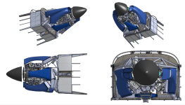
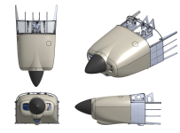
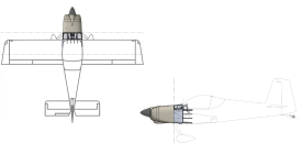
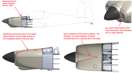
 
Last edited:
Back
Top