What's new
Van's Air Force

Don't miss anything! Register now for full access to the definitive RV support community.

Alternator field wire separate from alt output?

WingnutWick

Well Known Member
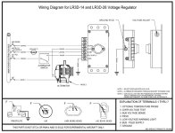
Installing a new B&C alternator and the instructions say “Take care to route the (alt output) wire separately from the field connector assembly”. Is this read as don’t run the two wires together or just clear from the connector assembly that plugs into the alternator? The previous setup had the two wires running together and I’m wondering if this was wrong?

Thanks all!
 
With an external regulator (which the B&C has), there is a theoretical risk of an uncontrolled overvoltage if the field wire and the output wire chafe against one another and wear through the insulation. If this happened, the field would see full output volts, and drive the alternator to the max, irrespective of what the regulator is trying to do. Switching the alternator off or pulling the field breaker has no effect.

I don't think they worried so much about this in the past but aircraft with all electronic instruments are much more common than they used to be.
 
Field wire

I ran mine outside of the starter cable firesleeve and in it's own insulation. No way to touch the alternator "B" circuit.
B&C alternator and regulator
 
a little drift but.... i think this is the way in theory an overvoltage starts from a short within the alternator. that is what ovm's are for i guess.
 
Not a EE

So, opening the Bus-Field Supply via the alternator switch would have no effect if the field wire on the alternator came in contact with the battery lead?

Also, I THOUGHT I remembered B&C stating it was OK to jumper 3 (Since) & 6 (bus field supply) and now they say either don't do this or not recommended?
 

Attachments

  • Screenshot 2023-07-15 184315.jpg
    Screenshot 2023-07-15 184315.jpg
    110.2 KB · Views: 59
  • Screenshot 2023-07-15 182809.jpg
    Screenshot 2023-07-15 182809.jpg
    34.1 KB · Views: 30
  • Screenshot 2023-07-15 182440.jpg
    Screenshot 2023-07-15 182440.jpg
    33.8 KB · Views: 26
a little drift but.... i think this is the way in theory an overvoltage starts from a short within the alternator. that is what ovm's are for i guess.

The OVM works by opening the breaker to the the FLD source. Any short that applies power to the FLD wire downstream of the breaker, including inside the ALT, will cause a runaway IF that source can provide enough current to do so (Alt output is regulated by current on the
fld input)
 
Practical likelihood?

Does anyone know how likely it is that this will occur in practice, i.e. alt output becomes connected to fld wire because both wires' insulation failed?
If this occurred then presumably the only thing that the pilot can do is turn off the master to protect the avionics from the OV condition.
 
Last edited:
Good Practice

In my short time in this sport, I have seen some pretty horrendous wiring firewall forward.
I think if good practices are used, and there are no chafing points of contact, this failure mode’s probability is down there with ignition switch failure. (Pun intended)
 
It is extremely unlikely that two parallel insulated wires would short together.
But if they did, shutting off the master switch would not do any good.
The electrical system is powered by the alternator, not the battery. So
disconnecting the battery will have no effect. And neither will opening the
alternator field switch because it is bypassed by the shorted wires.
 
my ovm disconnects the alternator b lead to the bus. an ovm wired to the field wire is not a surestop protection. i don't know if any of this is ever likely to happen but a ''hot'' field wire circuit would not prevent my ovm from working.
 
My Field wire is run separately from the B lead - however, at the alternator the two wires crossed each other right before the F went into the connector. The F was unsupported where they crossed and was touching the B. One day, I was inspecting wiring, separated the 2 wires with my finger. They were chafing against each other and about 1/2 the insulation was gone! Fixed and added support so they could not rub against each other. Lesson learned.
 
My Field wire is run separately from the B lead - however, at the alternator the two wires crossed each other right before the F went into the connector. The F was unsupported where they crossed and was touching the B. One day, I was inspecting wiring, separated the 2 wires with my finger. They were chafing against each other and about 1/2 the insulation was gone! Fixed and added support so they could not rub against each other. Lesson learned.

I would be interested to know what the root cause of this chafing (...and by inference, movement) was. Can you share pictures before/after?
 
Hello Brian - I’m not sure if I took a before/after pic, but will look after OSH (plan to arrive Friday, before show starts). If not, I’ll take a pic next time the cowl is off. The plane had over 1,000 Hobbs on it when I noticed the chafing. I’m assuming (hate using that word), it was caused by vibration over many hours and the F slowly “sawed” into the larger B wire. Wire is aviation Tefzel. The wires crossed at an approx. 90 degree angle, and it was a few inches from the F connector/plug in the back of the alternator. Both alternator and remote regulator are B&C, have worked flawlessly for me and have 1488 Hobbs on them. I have a heavy industry, electrical background and have seen many “bad things “ happen over the years - so I am always looking for an issue when I have an area opened up.
 
...I have a heavy industry, electrical background and have seen many “bad things “ happen over the years - so I am always looking for an issue when I have an area opened up.

Roger that!

I was curious, because I ran the field wire adjacent to the B lead, all the way up to the alternator, and only have about 1.5" or so of separation at the end where they diverge and go to their respective terminations on the alternator.

The entire length of the bundle is hung on adele clamps and two points along the sump/case halves above the intake runners, and the bundle is zip tied every 3 inches.

Aside from the difference in mass of the B lead and the field wire at the ends, I don't see an opportunity for resonance or movement....

Cheers!

B
 
don't turn off the master contactor

Does anyone know how likely it is that this will occur in practice, i.e. alt output becomes connected to fld wire because both wires' insulation failed?
If this occurred then presumably the only thing that the pilot can do is turn off the master to protect the avionics from the OV condition.

My thoughts:

Yes the likelihood of the field wire shorting to the B lead is very low with proper installation and periodic inspection but turning off the master would remove the battery which is the only thing holding the voltage down.

The B lead is connected to the main bus. An AGM battery will hold the voltage down for some time but a battery with a battery manager will disconnect itself fairly quickly. With the battery disconnected the voltage will rise into the hundreds and all electronics will be destroyed. The only thing you can do to shut down the alternator is stop it from spinning, turn off the engine and pitch up to stop the prop.

Let's say you're in cruise and notice an OV event, you have an externally regulated alternator with a crowbar, the field CB has not popped, turning off the alternator field does not fix the problem. If you turn on everything you have in order to reduce current going to the battery, reduce engine RPM hopefully to idle, look for a place to land ASAP, and have an AGM battery, it could work, you could throttle up if you're short on your emergency straight in approach. But that's a lot to think about and if you have a battery with a battery manager and dual electronic ignition that would be destroyed by a battery disconnect it's more of a concern.

If the field wire shorting to the B lead was a likely enough scenario one would develop an aircraft specific emergency plan to recognize and deal with it in flight but thankfully with proper installation and periodic inspection I'm willing to assume it will not happen.​

P.S.

A similar scenario can happen with an automotive internally regulated alternator that has no OV protection and an enable wire folks mistake for a field power wire. Start the engine, enable the alternator, then the only way to turn it off is to stop it from spinning. An OV event happens, crew turns off what they think is the field and the alternator keeps running. Or they turn off the master contactor also and the voltage goes into the hundreds. Ref an RV Allan Nimmo purchased: https://vansairforce.net/community/showpost.php?p=1415585&postcount=9

In this case the alternator would not restart with the enable switch turned off so Alan was able to restart the engine without restarting the smoke. And he had magnetos so no EI to destroy.​
.
 
Last edited:
Electrically dependent engine

For those of us with a EDE obviously this could be a very bad situation. Since I run 2 alternators 2 batteries seems I have 2 issues to address. If the pad mounted alternator shorts field to B lead it can't use any of the excess amperage generated to feed the main bus so it seems the voltage will keep climbing until the engine is shut down. (Pad mount alternator generates ~ 20 amps @ 2,200 RPM and I only need 12 to run the engine bus) My 2 buses are separated and with diodes only can feed primary to pad mount bus and not visa versa. If the main alternator would short, I could disconnect the pad mount and shed amps through that bus and turn on pitot heat and seat heaters to take some of the load. Seems I need to ensure the pad mount field never gets in contact with the B lead. I've set my alternator shunt alarms to 20 amps for the pad mount and 50 amps for the main bus to let me know ASAP I could have an over-voltage condition. Obviously have also set the voltages to give me an early warning.

Thanks, and appreciate the heads up,
 
Last edited:
i think it is strange all the talk about the 2 alt leads touching and making elect. contact. anywhere this happens it is bad. fuel pumps, ignition, navigation instruments.
the real issue about run away voltage is that it is caused by an internal short in tha alt. or a failure in the regulator. those 2 wires builders are talking about keeping so far apart get real close together in the alt.
it is my impression that a crowbar or some ovm is to protect from these internal failures. external wires are supposed to take care of themselves by good building practices.
 
Back
Top