What's new
Van's Air Force

Don't miss anything! Register now for full access to the definitive RV support community.

Superior cylinder rocker boss failure

Greg Arehart

Well Known Member
It was suggested in an earlier thread that I post the information on my rocker boss failure here so that it would be archived.

The short story is that I took off from Jean, NV on Dec. 14, 2010 after a normal preflight and runup. As I was on downwind preparing to depart the pattern, the engine coughed. Then coughed louder. I noticed #2 cylinder CHT and EGT was lower than the others (I don't recall the exact number for CHT but EGT was ~600; normal is ~1200 on takeoff with rich mixture). Shortly after, the engine began running somewhat rough. My thought was that this was fouled plugs or a fuel problem. There was never an obvious bang or pop or other loud noise that would have been more indicative of a failure. I circled near the airport, messing with the throttle and mixture, thinking I might cure the problem. When the problem didn't go away after a minute or two, I made a precautionary landing. Upon landing and exiting the aircraft, I found considerable oil on the L side and belly of the plane. I had lost ~2 quarts of oil in maybe 5-7 minutes. I don't know when the oil loss started, in fact, I was unaware of any oil problems until I shut down on the ramp and got out of the plane (I never lost oil pressure and ended up with ~4 quarts in the sump).

Upon opening up the cowl, it was obvious that the oil was coming from #2 cylinder head. Here is a photo of the damage to the rocker cover, which was impacted by the broken boss on both sides:


Closeup of the cracks (the obvious source of the oil leak):


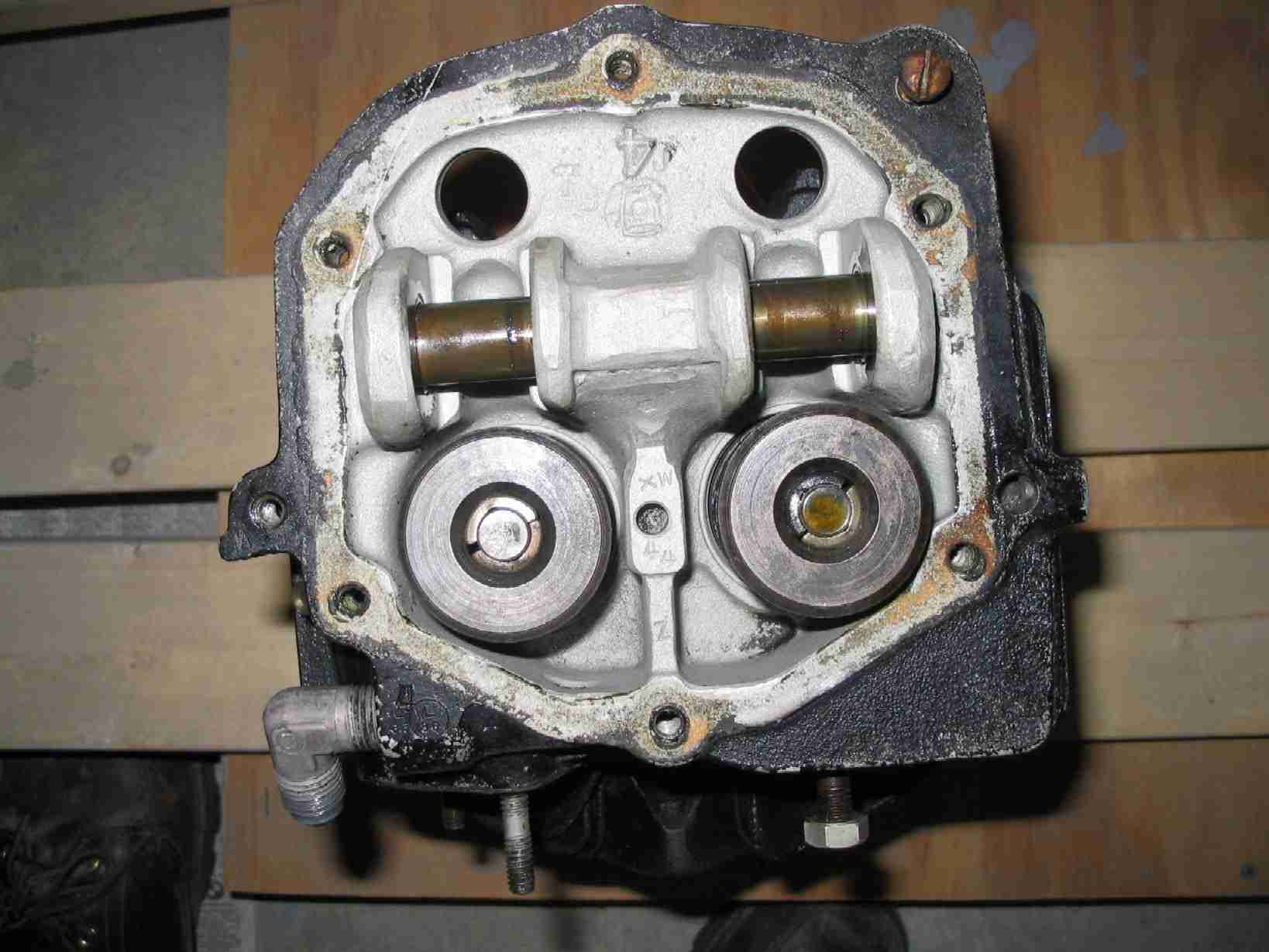
Upon opening up the rocker cover, it was obvious that the rocker pin boss had failed. Images of the failed rocker pin boss:


Here is the piece of the center boss:


Let me emphasize that at this point I do not know what caused the failure. There is no obvious damage to other parts of the cylinder head, but I have not done any detailed looking.

Some observations and data that may be relevant:

1) The casting looks coarser-grained than "normal" according to a couple of IA colleagues that have seen it. One mentioned a couple of potential inclusions in the casting, but this needs examination by a metallurgist.

2) The central boss is clearly thinner on one side than the other (see picture 5 above). Is this by design? Was the casting made off-center? Was the pin hole drilled off-center (rocker arms look like they have normal wear patterns)? I don't know the answers to any of these questions.

3) The engine (IO360) and cylinders were new, assembled by me under the supervision of a mechanic at a Superior engine build school in December 2007. The airplane first flew in December, 2008 and at the time of failure, the engine had 335 hours.


What are the implications for safety? Was this an isolated incident? As of today, I know that my other cylinders have similar serial numbers, so if there is an issue with the casting/metallurgy, I am concerned about potential failure of my other cylinders, which were likely part of the same casting lot. Anyone else having Superior cylinders that were cast in the same time frame might be cautious (I don't actually have the serial numbers in front of me). If/when I find out anything more on the casting, I will certainly post here. I have also submitted a Service Difficulty Report to the FAA.

Greg
 
Interesting

It looks like the shaft was machined way off center through the casting. The one wall is really thin compared to the other. Do the other cylinders have the same offset on the bore? Makes me want to check my Superior cylinders at the next annual.

Let us know what you find out.
 
Last edited:
It looks like the shaft was machined way off center through the casting. The one wall is really thin compared to the other. Do the other cylinders have the same offset on the bore? Makes me want to check my Superior cylinders at the next angle.

That thin wall was my observation as well. I do not know about the other cylinders, since I didn't pull the covers and look. But you can bet that I will be looking very closely at the other three cylinders when I get back there.

greg
 
Metallurgical

I've heard from USAF safety school graduates, who work accident investigations, the most important thing for something like this is do NOT put the pieces back together. It changes the molecular arrangement and therefore contaminates the sample and is no longer able to be examined for cause. Just a consideration. Jim
 
Ken,

Yes, I am working through Eagle Engines in Redding CA to be in touch with Superior. No direct contact yet, but I will call them Monday if Eagle has not gotten through to them.

Jim,

Thanks for the heads up on this. I have the pieces here at home and will not be letting them out of my sight until this is resolved.

greg
 
Good News

Greg, glad you made it through this potentially fatal engine failure. Good airmanship and a little luck. It was amazing to watch the post on here when you needed some help and see all the vafers chiming in to help, cell phones, aircrafts and stuff going on quickly. You got yourself some good friends here.

Good for you for making it back to land safe and sound, we will be interested in how this all pans out..causes etc.

Merry Christmas.
 
Greg,
The broken boss photo doesn't seem to show any beach marks. Grab a 10x magnifier and look close. See any on this boss or the other two? They would be somewhere along an edge and may not extend inward very far.

I can't comment on grain size, but a granular appearance with no beach is typical of a one-time material overstress. The off-center bore would certainly increase material stress on the thin side. All it needs is an event to push it over the limit.

Did this happen immediately after a power reduction?
 
Bobby,

I don't know for certain, but would hope that these cylinders were not part of the recall, since I built the engine at a Superior shop in December of 2007, but I don't know for certain. Good info to have and I'll check the serial #s when I am back down there.

Dan,

I'm not sure what beach marks would look like - can you clarify and I'll have a close look? If I recall correctly, I was just beginning to pull power back a bit. When the engine coughed, my first thought was fouled plugs and pulled mixture to try to clear the engine.

greg
 
Conceivably this could be a factor in a new AD on Superior cylinders and not related to the one posted above.

Does anyone have insight into how many cases of an event like this would usually result in an AD?
 
Last edited:
I'm not sure what beach marks would look like - can you clarify and I'll have a close look?

Beach marks form as a crack progressively deepens under cyclical loading. They look like the lines left on a beach as the tide goes out, thus the name. The origin will always be a point of stress concentration....for example, an edge, or inclusion, or pit in the surface.

The beach marks are formed before the part actually fails. When the crack gets deep enough, the remaining material can no longer handle the stress of another load application and the part fails with a snap. The snapped material shows a granular surface.


If I recall correctly, I was just beginning to pull power back a bit. When the engine coughed, my first thought was fouled plugs and pulled mixture to try to clear the engine.

Ok...I have a theory, but let's look for those beach marks first.
 
Greg,
I am very happy for a safe landing and excellent airmanship. Thanks for the info and I hope for a satisfactory outcome.
 
Dan,

No evidence that I can see of beach marks (and I use a hand lens for a living looking at rocks, so I have a quality lens). Some of the areas in the photos that appear to be coarser material, upon closer inspection, appear to me to be places where the metal was beat around, probably between the time of failure and before shutdown. The rest of the material is clearly a granular surface, but probably not as coarse-grained as it appears to be without a lens. I'll be interested to hear your theory.

greg
 
Superior AD

My reading of the Superior AD has it NA for the subject failure. Dan has Greg pointed on the right path.

A small portion of my forensic engineering work is analyzing mechanical failures to determine if the part broke and caused the event, or if the forces of a crash were sufficient to cause a "single event overload." For example, a common allegation after the car has run off the road and collided with the tree that jumped out in front of it, is that the blown tire, broken steering linkage or no brakes precipitated the event. We can tell by looking at the fracture surfaces whether there was fatigue or not per Dan's explanation.

We have a stereo zoom microscope if required, but most fatigue failures can be observed under fairly low power magnification. For extremely thin sheet metal (oil filter housing) the part was sent to a lab with a scanning electron microscope ($$$$$$$).

LarryT
 
Larry,

I also have a nice stereo microscope and access to an SEM if necessary to do photos etc. I have experience using this equipment, but not for looking at metallurgical issues. We do have a couple of metallurgists around, but they are mostly extractive guys.

I (and probably a lot of others) would like to know if this is a one-off event or is indicative of potential failure in (many) other cylinders.

greg
 
Stuck Valve?

Hi Greg,

It?s been interesting following this thread and also happy you got it down ok. My first thought when I saw this was that maybe you have a valve that stuck closed, something would have to give, often the push rod would bend but maybe this time the casting was the weakest part.
 
Conceivably this could be a factor in a new AD on Superior cylinders and not related to the one posted above.

Does anyone have insight into how many cases of an event like this would usually result in an AD?

No number of cases would do it if the FAA does not know about it....:)

Unless an accident found a similiar item, the only way the FAA would know about it would be through Service Difficulty Reports.

Since I assume the cylinder was OK for certified planes and not an experimental cylinder, perhaps a SDR should be filed...

http://av-info.faa.gov/sdrx/
 
No evidence that I can see of beach marks (and I use a hand lens for a living looking at rocks, so I have a quality lens). Some of the areas in the photos that appear to be coarser material, upon closer inspection, appear to me to be places where the metal was beat around, probably between the time of failure and before shutdown.

Common problem....the parts get thrashed enough to destroy visible evidence.

As Larry said, first task is to determine if it was a progressive failure or a one-shot gross overload. Let's go with "can't tell for sure", which leaves three possibilities.

Progessive failure due to defect (stress concentration). This one would usually leave beach marks, but they may have been obliterated.

Failure due to material stress above the fatigue limit in the thinwall section. After enough load cycles it breaks. Remember, aluminum has no knee in its SN curve. The root cause is casting or machining error.

...maybe you have a valve that stuck closed, something would have to give, often the push rod would bend but maybe this time the casting was the weakest part.

My thought too....the likely source of a one-time overload, and the third possibility. Easy to check. When you pull the cylinder, also try to remove the valves.

Most folks assume a valve sticks open, but in truth it merely winds up there after the valve train shoves it open and the spring doesn't have the muscle to shove it back. If any part of the valve train is weak, it bends or breaks. In this case you have a very thin wall on the pin boss....again, casting or machining error.

Whip out the glass again and look at all three broken bosses. Any sign of necking on the thin side, or a burr on the fat side?

 
Dan,

I can convince myself that there are small burrs on the thick side of the bosses, particularly the intake valve side and the center boss. I see no evidence of any necking on the thin side.

I also note that if one looks at the photo of the broken surfaces of the bosses in place, the upper right portion of the center boss has a lot of reflections, indicating that there are flatter surfaces there. The matching location on the broken boss (with me at home) is much coarser-grained than most of the casting. I had originally attributed this to the part having been beat around, but on further looking, it appears to me to be just some coarser crystals in the casting.

Having said that, the best burr I can see and feel is at this location, so my original hypothesis may be correct, that this coarseness is simply appearance resulting from the post-failure mechanical damage. This mechanical damage might also have resulted in a post-failure "apparent" burr at this location. I do not see a lot of other obvious post-failure mechanical damage to the parts.

I can also feel burrs (feeling seems to be more telling than seeing) on the upper left portion of this central boss, as well as on the furthest left (intake valve) boss. And there *might* be a burr on the upper part of the exhaust valve boss. In all three cases, there is clearly no burr on the bottom (down, thinner) side of the boss fragments that I have.

So, I'm presuming that if these are truly burrs from the break, that the bosses gave way starting with the bottom (thin) side, and the burrs represent the last material to break as the bosses bent upwards once the bottom half failed.

If hypothesis #1 is the case, then one would expect to see any beach marks on the bottom (probably outside?) of the lower parts of the bosses. There's not a lot of post-failure damage to these parts (i.e., they didn't get beat around too much). Can you give me a sense of what the scale of these marks might be? From what I can see with the lens, the surface is rough and granular at all of the corners and edges down to the <0.1 mm scale with a few exceptions which appear to be either larger casting grains or post-failure mechanical damage.

Obviously at this point I can't check the valves, but will do so when I get back to replace it.

Thanks for your input. Let me know if I can provide additional photos or evidence.

Sorry for the rambliness of the post, but I'm trying to give you the most complete observations I can.

Cheers,
greg
 
So, I'm presuming that if these are truly burrs from the break, that the bosses gave way starting with the bottom (thin) side, and the burrs represent the last material to break as the bosses bent upwards once the bottom half failed.

Me too.

If hypothesis #1 is the case, then one would expect to see any beach marks on the bottom (probably outside?) of the lower parts of the bosses. There's not a lot of post-failure damage to these parts (i.e., they didn't get beat around too much). Can you give me a sense of what the scale of these marks might be? From what I can see with the lens, the surface is rough and granular at all of the corners and edges down to the <0.1 mm scale with a few exceptions which appear to be either larger casting grains or post-failure mechanical damage.

The scale mostly depends on two factors, (a) the excess strength of the part compared to the normal cyclical load, and (2) ductility of the material.

A crack starts at a stress concentration. With each application of load the crack deepens. If the part has lots of excess strength (the part is massive compared to expected load) the beach marks may progress a long way through the section before the remaining material no longer has the strength to resist. Perhaps you would observe beach marks halfway across the section:


With little excess strength the beach marks may only extend a tiny distance. Note Larry's reference to sometimes using a microscope.

A very ductile material deforms and sort of re-routes the load path around the crack. Ductile materials tend to display obvious beach marks and a lot of necking. A hard, non-ductile material tends to fracture quickly, leaving few beach marks.

Sorry for the rambliness of the post, but I'm trying to give you the most complete observations I can.

And doing a fine job of it. Don't expect too much on my end. This is all just "Broken Parts 101". Lycoming doesn't call me for analysis ;)
 
Gil,

SDR has been filed.

Doug,

I don't know if pushrods are bent. Will have to wait until I get back to Jean to look at them.

Dan,

So, would this casting comprise a brittle or ductile type of alloy?

cheers,
greg
 
transportation

Greg,
Let me know if you need with transportation, I live in Sac area and will be back to town on Wed or Thursday the latest and I could fly you there if needed a ride. Of course providing the weather allows it.

530-471-5713 or [email protected]
 
Gil,

SDR has been filed.

Doug,

I don't know if pushrods are bent. Will have to wait until I get back to Jean to look at them.

Dan,

So, would this casting comprise a brittle or ductile type of alloy?

cheers,
greg

Chiming in for Dan here, that is most definitely a brittle failure. Cast aluminum (what our cylinder heads are made from) is more brittle than extruded alloys, though a nominally ductile material (say, mild steel) can suffer a brittle failure depending on how the load is applied. I have no personal direct experience with a valve boss failure due to a sticking valve, but in thinking about it that's what makes the most sense to me. The valve becomes the fulcrum at that point instead of the pivot. The load applied when the cam lobes forces the pushrod upward would be tremendous.

Here's a nice little explanation of failure modes:

http://web.mse.uiuc.edu/courses/mse280/notes/09/ch09_fracture.pdf
 
Valve cover records the event's immediate aftermath?

At least the orientation of the boss and/or direction of most significant energy. Since the valve cover damage is greater at the bottom of the impact site, wouldn't this indicate that the boss was turned slightly in flight and impacted there first, thereby transferring more energy there? Would'nt this confirm that the boss failed first on the lower (thinner) side, which caused it to start rotating as it left the casting?

Just speculating here but this suggests to me that the casting failed at the lower (thinner) side first, but not suggesting the actual triggering cause, except to say that whatever force caused this event to begin, was not enough to fail both sides of the casting at the same time. In other words, the thinner side failed, and it's dissapearance caused the thicker side to fail "some" time later.

Just my uneducated thoughts based on what I see in the pictures.

Bevan
 
I don't know if this helps anyone, but I pulled the valve cover off one of my cylinders (Superior XP parallel valve, delivered to me in January, 2007), made a couple of measurements and took some (blurry) photos. Based on my measurements, the thin area on the middle boss is about 1/8" thick. The top is approximately 1/32" thicker. At least you can see what one looks like before self-destruction. A local A&P walked in as I was taking the photos. He'd never seen a valve cover off one of these cylinders before. He observed that the Superior bosses look completely different than the ones on Lycoming heads. Having never seen the latter I can't comment.

1131790246_yJSdW-L.jpg


1131790245_edrrA-L.jpg


1131790346_9CWZ2-L.jpg


1131790348_cbwAd-L.jpg
 
bosses

I just took a cursory look at four scrap wide deck Lyc 0 320 cylinders. Its a little hard to see from the pictures, but clearance for the rocker covers and valves springs precludes the rocker bosses from being symmetrical. The outer bosses have clearance for the rocker covers on the upper portion and for the valve springs on the lower portion.
The material on the failed cylinder on the center portion below the rocker shaft does appear thin.
If any significant error existed on the location of the rocker shaft bore, the valves would not open the proper amount. It would be interesting to cut up a junk Lyc cylinder to compare.
 
cylinders

The pictures posted by Lars look different than the failed cylinders. It appears that superior machines some areas that are not machined on Lycomings. Hard to tell for sure. If you look closely at Lars pictures you can see the angle for clearance on the valve springs on the outboard bosses.
I emailed Mahlon Russell asking him to take a look and possibly comment.
 
Continued thanks for all the input on this.

My rocker bosses (well, three of them anyway) look like the ones shown in Lars' photos, very different from Bill's Lycoming O290 bosses. It is clear that the bottom half of the bosses failed first, based on the damage done to the cover, coupled with the burrs on the thicker, upper side of the bosses. And that makes sense given the metal thickness. I measured the thickness of the bottom of the center boss, and its slightly more than 1/16 inch at the break. The thick side is slightly more than 3/16 inch at the break. No machining has been done on either side of this boss - it is clearly the original casting surface present. I see no (obvious) reason that the bottom of the center boss needs to be so thin, but I am not an engineer or metallurgist. Certainly there is no (obvious) reason in terms of clearance from other parts.

My hypothesis is that the bottom of the bosses failed first, maybe because of a stuck valve. Because of the tight fit of the rocker cover, it may have held the fractured bosses mostly in place and maybe allowed the cylinder to continue to operate for a limited time afterward. Eventually the cover deformed sufficiently (and the bosses were abused sufficiently) to allow the bosses to completely fail. Whether that was fractions of a second or minutes after the initial failure is unclear. And once the rocker cover split, I started losing oil.

At this point, my plan is to arrange for a replacement cylinder, inspect the rest of the engine for potential damage, including a close look at the other rocker bosses, install the cylinder, and try to fly home IFR along highway 95. I've had many offers of assistance of various sorts, for which I am appreciative, including an on-ground check of the airplane by Shawn Franklin (who reports that all is secure).

Cheers,
greg
 
Greg, additional info, perhaps more as an FYI and some armchair analysis than anything... the pin bushings on mine are .75" OD. I am confident that what we are referring to as the "thin area" is closer to 1/8" thick on mine. As if the casting mold moved when your cylinder head was made, or perhaps a running change was made in the design of my cylinders compared to yours. In the automotive world (thinking about cast iron American V8 blocks) that movement did take place sometimes, and they called it core shift. Not sure if that applies here.

In any case, with a caliper, a straightedge and a sharpie it's pretty easy to estimate the thickness in various places, once you get back to your plane. Since I have Superior cylinders (attached to my Superior XP IO-360 engine) I have more than a passing interest in this. If there is anything else I can measure that might be of help, let me know.
 
Engineering Investigation

Be careful whenever you have ANY part failure. If you take the parts and put them back together like a puzzle piece you make it much harder (usually impossible) to determine 100% what the failure mode was. When there is brittle fracture, etc the metal parts have a very dull look to them, this is a bunch of microscopic ridges and valleys. When you put them back together you "bulldoze" the ridges into the valleys and the examiner cannot tell you with as much certainty the cause. This is why NTSB gets there ASAP and doesn't let anyone touch the stuff until they get parts for t he investigation.
 
The pictures posted by Lars look different than the failed cylinders. It appears that superior machines some areas that are not machined on Lycomings. Hard to tell for sure. If you look closely at Lars pictures you can see the angle for clearance on the valve springs on the outboard bosses.
I emailed Mahlon Russell asking him to take a look and possibly comment.
I think the failure could be from a defective cylinder, a stuck valve or excessively worn rocker shaft and bushing.
I don't know of a tolerance for Lycoming rocker boss wall thickness but that picture looks fairly thin. TCM had a min. center boss wall thickness of .18 inches on the O-200/A65 style cylinder. I don't see why the boss loading would be any different on a 320 or 360 cylinder so you would think a min wall thickness around that amount would be in the ball park.
Good Luck and Merry Christmas,
Mahlon
"The opinions and information provided in this and all of my posts are hopefully helpful to you. Please use the information provided responsibly and at your own risk."
 
Update on the cylinder issue.

After getting no response from Superior (the Eagle Engines guys have been calling continuously since Friday, Superior secretary has promised calls will be returned, but it hasn't happened), Lou at Eagle is ordering me a new cylinder assembly from ECI. I hope it arrives by next Monday and, if so, plan to go to Jean as soon thereafter as possible to install and get my airplane home. At this point I am presuming I will be paying for this, in case anyone wondered. And that is acceptable to me since we still don't know the cause of the failure.

Assuming that we don't find the obvious cause of the failure when I return to Jean, once home with the limp cylinder and parts, I will continue to pursue understanding the cause. Obviously I will also be checking the other 3 cylinders closely before flying again.

greg
 
I think the failure could be from a defective cylinder, a stuck valve or excessively worn rocker shaft and bushing.
I don't know of a tolerance for Lycoming rocker boss wall thickness but that picture looks fairly thin. TCM had a min. center boss wall thickness of .18 inches on the O-200/A65 style cylinder. I don't see why the boss loading would be any different on a 320 or 360 cylinder so you would think a min wall thickness around that amount would be in the ball park.
Good Luck and Merry Christmas,
Mahlon
"The opinions and information provided in this and all of my posts are hopefully helpful to you. Please use the information provided responsibly and at your own risk."

Update on the cylinder issue.

After getting no response from Superior (the Eagle Engines guys have been calling continuously since Friday, Superior secretary has promised calls will be returned, but it hasn't happened), Lou at Eagle is ordering me a new cylinder assembly from ECI. I hope it arrives by next Monday and, if so, plan to go to Jean as soon thereafter as possible to install and get my airplane home. At this point I am presuming I will be paying for this, in case anyone wondered. And that is acceptable to me since we still don't know the cause of the failure.

Assuming that we don't find the obvious cause of the failure when I return to Jean, once home with the limp cylinder and parts, I will continue to pursue understanding the cause. Obviously I will also be checking the other 3 cylinders closely before flying again.

greg

Greg:

As Mahlon said, check the valves. See Lycoming Service Bulletin 388. Your IA friend may have the tools to lend you. As I under stand it, tight valves typically show up in the first 100 hours and I would not expect that your 300 hours would not be the cause.

If you retrieve your airplane between Christmas and New Years, I maybe able to lend a hand. I have all the tools needed to change a cylinder and the tools for the valve wobble test described in SB388.
 
Last edited:
Be careful whenever you have ANY part failure. If you take the parts and put them back together like a puzzle piece you make it much harder (usually impossible) to determine 100% what the failure mode was. When there is brittle fracture, etc the metal parts have a very dull look to them, this is a bunch of microscopic ridges and valleys. When you put them back together you "bulldoze" the ridges into the valleys and the examiner cannot tell you with as much certainty the cause. This is why NTSB gets there ASAP and doesn't let anyone touch the stuff until they get parts for t he investigation.


Sounds like a safety school grad there. HT's?
 
Hey Greg,

Tagging on with Gary, if you need help between Christmas and New Years, we are hoping to be at the cabin, which isn't far. Hoping, that is, if the rains in SoCAL will ever let up! I'm expecting the EAA to start sponsoring ark building events soon....

Paul
 
Thanks all for the offers of help. I'll gladly take whatever help I can get. Everything is dependent on arrival of the cylinder plus the weather. I will keep you all posted.

Paul, that rain is a sign that some of the SoCal pilots need to consider getting their float rating as a "to do" for 2011!

Cheers,
greg
 
Greg you can add me to that list. I'm trying to avoid work as little as possible between now and after Jan 3rd, so if you need a wrench turner or anything else, feel free to ask.
 
Dye Penetrant Testing

Greg,

Would doing a dye penetrant test on the other cylinders be something you might want to do before your trip home but definately once you get home to look for those hair line cracks.

Just a thought.
 
Greg, glad nothing worse happened, and hope for a swift and safe return to flight shortly.

If that were my plane, I'd check the camshaft, lifters, and pushrods for damage incurred during this unfortunate incident, lest I encounter other unpleasant incidents later. Here's hoping all is well.
 
Greg,

I'll be looking into doing these tests to determine if there is potential other cylinder damage.

Joel,

Suggestions on how to check the cam short of a complete disassembly of the case and what to look for?

greg
 
Greg, a borescope would be best, but lacking that, you should be able to spot any obvious nicks or scratches on those two lobes after you remove the lifters.
Don't use a magnetic tool or screwdriver to remove them. That will magnetize them, which is not a good thing. I don't recall the proper tool for removing them. Perhaps some of the Lycoming guru's can chime in with more specific and approved tools and procedures to accomplish this.
 
Greg,

First, I'd like to say that I enjoyed your RV BBQ at Reno last year (2009). Bobby Willis and I flew his RV6A out to Reno from Quincy, Florida. We enjoyed our time there and your BBQ was great. It was nice to meet some of the faces I see on this site. RVers are a super bunch of folks.

I'd like to make a very uneducated comment about your rocker shaft boss failure. Please understand that I know very little about aircraft engines...my time has been spent building race engines for dragsters.

It looks to me like the bosses on your engine are made more "light duty" than some of the other bosses that are shown in pictures here. The rocker shaft bosses should never fail like yours have. If a valve stuck and it overcame the integrity of the boss, the destruction of the boss should be in the opposite direction from the stuck valve......from the thinner boss diagonally across the bosses with the thicker boss on the unstuck valve being the last to break off. The burrs on the thicker boss should indicate the break in that direction. More than anything else though, the bosses appear to be much too weak if they failed before the push rod bent. I cannot imagine that the binding force of a stuck valve could overcome the integrity of the boss. Also, it does not make sense to me that the cylinder manufacturer would not make the bosses with the same amount of material all the way around the rocker shaft bore. It looks like the cylinder moved slightly when the rocker shaft bores were machined. I'm just thinking out loud here.

Anyway, I wish you the best with the solution. You do a very nice thing by entertaining RVers at Reno with your BBQ. Thanks again for your hospitality.
 
I have a hangar full of tools at henderson airport. Let me know if I can help. Seven 02 278 zero 273
 
I have a borescope if you need it

Someone mentioned using a borescope for your inspection. I have a video Borescope if you'd like to use it when you come back down here.

Seb Trost
Boulder City, NV
 
Cause investigation.

Since there were bushings pressed in those bosses, I would see if you can measure accuately, the diameter of those rocker pin bores and the bushing O.D.. A good machine shop could do this since they are broke in half.

Being a tool and die maker, I have seen several times when a pin or a bushing was pressed in too tightly in a die, it would brake the part. The forces are pretty incredible in a tight press fit.

Also if the interferance fit was tight and heat was used to expand the aluminum for the assembly of those bushings, it could be possible to over heat the aluminum and change the temper making it weak. Looks to me this might be the case here. Just guessing.

Steve
 
Back
Top