Hello, I purchased and have owned an RV-10 for about 10 years now and am still learning!
Every setup of the shunt/current limiter combo that I have seen is set up the same way (including mine) with the alternator b-lead going to the shunt first, then to the current limiter, then to the battery side of the starter solenoid. My question is: can these be reversed? Can the primary alternator b-lead go first to the current limiter, then the shunt, then finally to the starter solenoid?
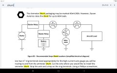
Why on earth would I want to do this, you ask: I have recently installed a backup alternator (Monkworkz generator) and I have the MZ output going to the same point on the shunt where the b-lead of my primary alternator is attached. The problem I see with this is that if the primary alternator and/or the current limiter fails, then I have no backup alternator. If I could run the primary alternator to the current limiter first, then to the shunt, I could then take my MZ output to the shunt, bypassing the current limiter. See attached picture.
You ask, why don't you just run the MZ output directly to the starter solenoid? I did and that is still an option. I also ran the proportional output from the MZ voltage regulator to the Hall Effect input on my AFS 5600. AFS gave me a custom setup for the Hall Effect so that it is calibrated to the MZ, but my amps are still way off - by about half. I will get back with AFS to play with this custom setup, but I am also not crazy about how AFS displays 2 amp readings. When I setup the screen for Amp1 and Amp2, the vertical bar displaying the amp reading is cut in half, lengthwise, so it is really skinny. Amp1 displays on one side and Amp2 displays on the other side. The number value of the amp reading below the bar toggles about every second between Amp1 and Amp2, so I might see 17 amps, 0 amps, 17 amps, 0 amps, ......... as it toggles between the primary and backup alternator readings. I know it's a small thing, but I'm just not crazy about that display.
Anyway, does anyone have thoughts about reversing the shunt/current limiter order to the primary alternator going to the current limiter first?
Thanks in advance for your input!!


