What's new
Van's Air Force

Don't miss anything! Register now for full access to the definitive RV support community.

Home brew engine dehydrator

Desert Rat

Well Known Member
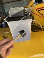
I've got quite a bit of travel coming up and my engine has been out of the bag for going on 6 months now. Based on that, I thought it wouldn't hurt anything to throw together an engine air dehydrator as I've seen others do.

This was all made with amazon and dollar store parts and literally just thrown together with duct tape in the short time I had before leaving on a trip. Total cost was about $80, with the desiccant being the most expensive component by a large margin. I'll pretty it up with an actual base and frame at some point.

Full disclosure, I've also got desiccant plugs in the upper spark plug holes, but I've never been convinced that they really do much to help with what might be going on down in the guts of the engine.

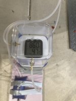
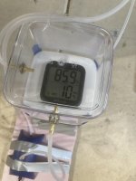
The humidity drop after only a few minutes of operation is pretty dramatic, although I have to confess I'm a bit skeptical of any reading I get from a $10 battery powered hydrometer I got from Amazon.

I originally got fancy and had this running a few hours a day on a timer, but the humidity would come up to about 20% within a few hours of the pump shutting off. I suspect theres a good chance this is just ambient air leaking around the lid seals on the cheap dollar store food canisters, but at any rate, for now I just ditched to timer and let it's do it's thing 24/7.

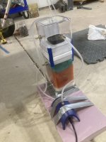
The white and green stuff sandwiching the desiccant are just some scotchbrite pads that serve no purpose other than to keep the desiccant from sloshing around in there.

The plumbing pulls air from the breather tube into the gauge chamber, then into the pump, then through the desiccant chamber, then back into the dipstick tube.

Not making any claims about whether this is necessary or not, but I figure it cant hurt.

edit- in case it's not clear; picture 2 was reading ambient temp/humidity before I plugged it in. Picture 3 was about 10 minutes after flipping the switch.
 

Attachments

  • IMG_8627.jpg
    IMG_8627.jpg
    299.4 KB · Views: 299
  • IMG_8628.jpg
    IMG_8628.jpg
    227 KB · Views: 201
  • IMG_8629.jpg
    IMG_8629.jpg
    193 KB · Views: 198
Last edited:
I originally got fancy and had this running a few hours a day on a timer, but the humidity would come up to about 20% within a few hours of the pump shutting off. I suspect theres a good chance this is just ambient air leaking around the lid seals on the cheap dollar store food canisters, but at any rate, for now I just ditched to timer and let it's do it's thing 24/7.

edit- in case it's not clear; picture 2 was reading ambient temp/humidity before I plugged it in. Picture 3 was about 10 minutes after flipping the switch.

That's the only way to keep the humidity level down. Unless you want to build a vacuum stable container.
 
plumbing connections to engine?

So how do you make the plumbing connections to engine?

Supply and return?
 
I noticed that too, no pictures of the connections to the engine. Do a search on this topic in this forum because there's lot of info on this. We've written about it many times and there are tons of pictures of different ideas of the same thing.
 
Dehydrator

Just another variant for anyone interested.

Mine is open loop. I couldn't figure out a way to connect to the crancase vent with the cowl in place. The vent terminates very close to the exhaust pipe.

I used the biggest pump I could find. The line is connected to a fitting on a 3D printed oil cap tapped for 1/4"NPT. Air just vents out the crankcase vent. We are pretty dry but last time I measured it was about 40% going into the dessicant and 10% coming out the crankcase vent.

I doubt I will run it 24x7. I figure 30 minutes cool down after flight then connect and run it on a timer to come on for 15 every hour or two.
 
So how do you make the plumbing connections to engine?

Supply and return?

Due to how close the breather downspout is above the exhaust I really couldn't see any effective way to do this as a closed loop unless you either get into the breather hose at mid-span or take it loose from the firewall so you can get clearance to get into the end.

Here's what I ended up with. This wouldn't be convenient for a flying airplane, but thats not what I'm talking about here. I just want keep the humidity low inside the engine while I'm still in the build phase.

suction side:

Got an appropriate size rubber plug at ACE hardware. Drilled a hole in it. Shoved suction side aquarium tube through. Pulled the crankcase breather hose off the downspout at the firewall and stuck the plug in the end of it.

return side:

Bill Wood (decathlon737) made a bunch of 3D printed caps that screw into the oil filler tube in place of the dipstick a few months back and was mailing them to anybody who asked for one. I put a hose barb in one and stuck the return side line on it.

Both lines just got taped to an exhaust pipe out of harms way so I can get the cowl on and off without tearing them up.

ezee peezee.
 
Last edited:
Crankcase breather

Due to how close the breather downspout is above the exhaust I really couldn't see any effective way to do this as a closed loop unless you either get into the breather hose at mid-span or take it loose from the firewall so you can get clearance to get into the end.

Here's what I ended up with. This wouldn't be convenient for a flying airplane, but thats not what I'm talking about here. I just want keep the humidity low inside the engine while I'm still in the build phase.

suction side:

Got an appropriate size rubber plug at ACE hardware. Drilled a hole in it. Shoved suction side aquarium tube through. Pulled the crankcase breather hose off the downspout at the firewall and stuck the plug in the end of it.

return side:

Bill Wood (decathlon737) made a bunch of 3D printed caps that screw into the oil filler tube in place of the dipstick a few months back and was mailing them to anybody who asked for one. I put a hose barb in one and stuck the return side line on it.

Both lines just got taped to an exhaust pipe out of harms way so I can get the cowl on and off without tearing them up.

ezee peezee.

For those contemplating a closed loop system on an operational engine, the crankcase vent has a bypass hole. At least it should. Usually 6" above the end. Maybe it's a non issue, but the system would pull air through both the vent and the bypass hole. Just another data point.
 
So how do you make the plumbing connections to engine?

Supply and return?


I have a 3D printed cap that screws into my oil dipstick tube...this is where the dehydrated air is pumped in. For awhile, I returned air to the pump with some poly tubing that slipped nicely over the output tube of my oil separator. I ultimately decided that it was too much of a PITA to get under the plane to plug it in after a flight, so now I just run it open-loop. Works fine.
 
Another take on the same idea

I built this a few weeks ago & meant to post about it, but I forgot until I saw this thread. Also built entirely with components from Amazon. Since these pictures were taken, I have replaced the smaller return air reservoir with an even smaller (5 oz) container to reduce the sensor lag.

3D-printed threaded oil filler cap & tapered exhaust plug.

I have the Antisplat oil separator and crankcase vacuum kit installed, so this provides an easy way to do a closed-loop dehydrator, with the exhaust plug easily accessible with the cowl on.

Dehydrator1.jpeg


Dehydrator2.jpeg


Dehydrator3.jpeg


OilFillerPlug.jpeg


ExhaustPlug.jpeg
 
Hi David, what humidity are you getting with this system?

Take a look at the second picture above - 10% at the intake/return & the output sides. This was after the system had been running for a few hours. The first picture shows 88% (I think) at the return- just after shutting down the engine & hooking up the system.

This is in Georgia, where the humidity stays high most of the time.

These are $2 hygrometers; not sure how accurate they are. I'm ordering a better set of sensors & a data logger to see how long it takes for the humidity to come down.

Current hygrometers (Amazon)
 
A couple of pictures of the smaller return airbox

Note that no fancy (and expensive) tubing connectors are used. I drilled slightly undersized holes in the plastic containers & poked the plastic tubing through. I found that cutting the tubing ends on an angle helped get them through the undersized holes. We're not pulling a hard vacuum here, and what's the worst that can happen? We get a little ambient-humidity outside air into the system. If it makes you feel better, smear a little clear silicone sealer around the connections.

I put a filter inline between the desiccant chamber & the air pump. Don't want any desiccant dust getting into the pump or the engine.

I've become convinced these $2 Chinese hygrometers probably only read down to 10%. I've never seen them read any lower. Better humidity sensors are on their way & will be installed next weekend.

Dehydrator4.jpeg


Dehydrator5.jpeg
 
Mine is pretty simple. Pump ambient air in the bottom, through 15 lbs of silica gel, then out the top into my dipstick tube. I lay a hygrometer in the container on top of the gel and when it starts reading above about 18% and the gel turns a little pink (about 10-12 weeks in the summer), I exchange the pink gel for the other 15 lbs and cook the pink stuff. I'm always pushing dehydrated air (12%-18%) through the crankcase 24/7. I don't bother with a return line anymore -- only advantage was dehydrating the gel a little less frequently.

(I don't use the stopper in the dipstick anymore...just recently got a threaded dipstick plug from Steve Melton, although the stopper worked just fine)

..
 

Attachments

  • IMG_8472.jpg
    IMG_8472.jpg
    231.1 KB · Views: 31
Last edited:
Back
Top