What's new
Van's Air Force

Don't miss anything! Register now for full access to the definitive RV support community.

Engineering Assessment Document and additional info

scsmith

Well Known Member
To help get the various conversations about Laser-Cut Parts organized better, I am starting this on a new thread, and I deleted the post in the original thread. Note some serious edits here in this version also.


I just read the Engineering Assessment Document.

It talks a lot about fatigue characteristics, and useful life vs loads, all the classical stuff. But it seems to me that there is a problem with the analysis and assumptions, at least as presented in the document.

"Normal" fatigue analysis predicts the life of a part that starts out as a good part. It likely has stress risers, small defects that will eventually initiate a fatigue crack. A large fraction of the useful life occurs with no crack. At some point, a crack is initiated, and over time, grows to the point where the part fails. The portion of the useful life of a part once the crack forms is, I believe, fairly short compared to the portion of the life prior to the emergence of the crack.

So I'm not convinced the analysis and assumptions and testing presented in the document is meaningful for the case where a part begins its life with a crack.

Further thoughts:

I hope I did not give the impression that I thought that the Vans analysis, testing regimen and assumptions are improper. I'm sorry if I did give that impression. My point was only that the document itself didn't convey to me that they had considered the differences in fatigue characteristics when there is a pre-existing crack. I'm sure they did -- they are good, smart engineers, and it would always be the goal of the analysis and testing to replicate as closely as possible the actual circumstances under study.

By its nature, the Engineering Assessment Document is an overview, attempting to convey the scope and detail and rigor of the work they are doing. At the same time they have to provide enough background info so that folks can understand why it is that the testing is meaningful. Thus the general overview discussion about classical fatigue life testing and analysis.
I imagine that letting the 'public' in on intricate details of testing and analysis is a two-edged sword. But it would be interesting (to me at least) to have more insight into the particular test specimens that they are testing. I was hoping the document might have more of that. But I think we should have confidence that the testing they are doing IS meaningful and representative enough to draw engineering conclusions from. It wouldn't make sense for the company to make the investment to do the tests if they weren't.
 
Last edited:
More thoughts on dimple cracks

It is important to recognize that the cracks occurring when the dimples are formed are, of course, NOT fatigue cracks. They are cracks that occur during the plastic metal-forming processes where the material is obviously loaded beyond its yield strength. Localized stress concentrations may cause the local stress to exceed the ultimate strength, and a crack forms.

Whether or not that crack grows, or propagates with time depends on the stresses that the area around the crack 'feels' in service. If the strain energy at the tip of the crack is not sufficient, then the crack will not grow. If testing shows that after being exposed to the equivalent of many expected service lives of the parts, the eventual fatigue failures are at other places in the parts, and NOT at the dimple cracks (the document alludes to this somewhat), and furthermore that the behavior of the LCP and the equivalent punched parts are similar, then it would be a totally reasonable engineering decision to say that the parts are acceptable for use. It may seem concerning, but if testing shows that those cracks don't grow, then they are not a problem for airframe life.

One might then ask why general construction guidance is to prepare holes (deburr, etc) to prevent cracks. Well, it is still just good building practice. And it may be that the details of dimples with and without cracks have never before received so much scrutiny, so without this new experience and evidence, an abundance of caution would have, in the past, dictated preventing dimple cracks.
 
Thanks for sharing your thoughts Steve. I'm not an engineer but your points are well taken. I wish Vans would have included something similar in their Engineering Assessment.
 
Steve,

I'm glad to see I wasn't the only one wondering if I had missed something in the assessment. I'm also an aerospace engineer with primary responsibility for this kind of analysis (albeit rocket engines, not airplanes) and I agree with all your points. The analysis of pre-existing cracks (what we typically call fracture analysis) is distinct from the analysis of when a crack will occur (fatigue analysis), and remaining life is exponentially lower for a part with pre-existing cracks in it than one without.

I don't necessarily expect Van's to share all of their technical data with us and I understand that they're communicating complicated technical content to a wide audience with varying backgrounds, but the assessment seems to ignore pre-existing cracks other than the Residual Strength Testing section where they cut sections to address static strength when cracked fully through. I suppose if the risk assessment is based entirely off consequence of failure for primary vs. secondary structure (replace primary, secondary is okay even if it cracks through), rigorous fracture analysis of crack propagation isn't required, but it would be reassuring to have that rationale explicitly spelled out.

Another element that I don't see explicitly addressed is the second-order effects of cracks - whether potential load redistribution from cracked structure could meaningfully reduce fatigue life of parts in a way that would not have been screened by the residual strength testing, which was just a static load. I'm pretty sure this is implied in the assessment but would appreciate clarification that this was evaluated.

This is a difficult problem and I don't envy Van's. For my part, I place much more weight on the solid history of the fleet made with punched parts than on the necessarily limited testing and analysis on a new issue - I've dealt with many cracks that defied our expectations and resulted in unexpected catastrophic failure of components. Granted, that's a bit of an apples to oranges comparison given the relatively low margins of safety in rocket components vs. airplanes, but regardless - for my peace of mind, I'll be replacing all laser-cut components on my RV-14 to make sure the pedigree is consistent with the robust history of the fleet.
 
Wow. Great thread with very intelligent folks.
Let me dumb it down if I may. I inspect a plane and find any crack. It must be addressed in 1 of many ways depending on guidelines provided by…? Not these tests. So stop drill a few here and there. No big deal. But there are a multitude of limits to repairs that I believe are not even addressed in these tests. I don’t believe that what the intent was and I hope that folks realize these are not install and forget pieces. Nor is any part installed on any aircraft. But when I go to dimple a part and see a crack. I cannot refer to this testing and say it’s going to be hidden by the rivet I set and therefore consider it ok? I don’t believe that is what they are saying?
So having said all that mumbo jumbo.
To any of you very intelligent folks that understand these test results far more than I. Do they actually say cracks are good or just lcp without cracks can last just as long as punched parts without crack? I apologize if it’s been answered already.
Thank you
 
Crack Propagation

Another element that I would have like seen tested was the effects of vibration fatigue and it's affect on crack propagation. Placing test articles under static loads and inducing vibrations to closely replicate the normal rpm range of an engine could help to determine if certain operating conditions cause the cracks to occur sooner.
 
Steve, Matt- thank you for your time and obvious expertise. You are adding immeasurable value to the conversation.

In a previous life, I wasn't the one generating the analysis, but I was responsible for signing off on nonconformities and issuing a military flight release. Often, the part was obviously OK, but could only be released via one of two paths:

  • Perform analysis or testing (similar to what Van's did) to release that specific part.
  • Update the documentation to allow features represented by this part as part of our normal acceptance

What I'm struggling with is that Van's appears to have done #1, which would be great for any specific LCP, but is moving forward with #2 - fleet/inventory-wide acceptance of a wide range of part and build quality. If they just went a step further and formalized what they've learned about small cracks in dimpled holes, then updated the build guidance to give some standard to accept against, a lot of the uncertainty would go away.

As is, I read the test report as verifying that Vans aircraft are even more bulletproof than anticipated. This is awesome, but it still leaves some questions about how I/we build them.

Do they actually say cracks are good or just lcp without cracks can last just as long as punched parts without crack?

This question above hits at the core of my concerns right now. I didn't design the airframe, I'm not an A&P, and all I have to rely on before I risk my family in a homebuilt aircraft are the published and generally accepted build practices. Far more than the disposition of any given LCP, I'm feeling a bit unmoored by the grey area Vans is exploring - what is the standard? Would you close up an airplane with known cracks? How many, how big?

There are tests and analysis that could answer these questions; I suspect Vans has performed many of them. I hope Vans continues to present their findings and reduce this uncertainty. I really don't want to disassemble my wings, but I need to know when I strap my wife in that I met the build standards anticipated when the aircraft was designed. I no longer know what that standard it.
 
Last edited:
If one of Vans goals is to replace as few parts as possible, they should make sure we feel comfortable with what we have. That takes communication.

Vans never did share a recording of the presentation at Oskhosh (which Greg told me Vans would do when talking to him face to face). The final engineering assessment document had much less detail than what Ryan discussed at Oshkosh. As a mechanical engineer for 25 years, for me to fully accept the "acceptable for use" classification on parts I would like to see more information presented. A video by Ryan finishing what he started in Oshkosh would do it for me. If that happens I'll request much fewer parts.

I have seen no guidance for a part listed as "recommended for replacement" that is already riveted in place with no cracks. Is this part still "recommended for replacement"? Again, more information about the test results would make it easier for me to leave some of these parts in place and not request replacements.
 
My interpretation of this document was that:
- The “analysis” was done to determine where the stress concentrations are in the parts (not at the dimple rim, apparently) and to establish the expected fatigue life of the parts and their respective structures (without cracks, i.e. optimistic).
- The “testing” was done using representative LCPs and structures (with cracks) to determine whether LCPs met the fatigue life expectations established via the analysis.

I freely admit that I can’t be certain that my interpretation is correct and that, regardless, I’m woefully unqualified to determine whether the approach or its findings are appropriate and valid (true of nearly every builder I suspect, which is a significant factor to this issue in general).

Interpretation aside, this document is an executive summary, no more. I find it somewhat silly that Vans provided more detailed information two months ago when Rian presented at OSH than they are providing now as the culmination of all of this testing they have asked the community to wait patiently for.

I humbly suggest Vans should at least prepare and host a live webinar on this topic to review the testing, findings, and conclusions. Such a webinar would ideally be a significantly extended and enhanced version of what we saw at OSH, and would preferably include Vans collecting questions from the community formally in advance of the webinar (so as to address the common questions during the presentation) AND allow for live Q&A.
 
Thx for starting this thread!

I do have one question one of the experts on this thread might be able to answer.

What is a crack?

I know this sounds philosophical and I am not trying to aggravate the people impacted by the LCP issue but I am truly trying to figure out if there is a standard for this. At large enough magnifications any surface I have seen is uneven. Depending on the surface preparation the magnification needs to be larger or smaller.

So at what size do we consider those unevenness a crack we should worry about?

Is there a standard for that?

In the past with punched holes we match drilled, deburred and dimpled them and if you could not see any unevenness with the naked eye we called it good. At least I did. Was that the correct practice or should I have gotten out a magnification glass to look over them?

Thx

Oliver

Now you're getting to the meat of it. For almost all of manned flight history with metal airplanes, we've been good with visual inspection with a Mark I (and occasionally Mark II) eyeballs. Cracks were either there, or they weren't. Simple. Now we've got a good portion of the homebuilt community using 10X loupes on everything and buying 400X microscopes off Amazon, and if somebody pulls out an SEM I can pretty much guarantee EVERY part will have cracks somewhere regardless of the method of creation.
 
Cracks are nothing new..

While we all dislike the current hole crack chatter, its not likely to create RV's falling from the sky. Most production aircraft have developing cracks for various reasons, some for production anomalies, and some wear/tear, and we deal with them through various means of inspections, and MFG Service data. I have 45 years as an aircraft structural SME in Heavy jets and GA/EXP. I have been involved in the Aloha 737-200 skin departure and Boeing Legacy 737 series ongoing skin cracking issues for decades .I used to refer to them as "a series of cracks flying in formation". Also the DC-10 series horizontal stabilizer machined skins which live under 90 day re-inspections and summation of developing crack length/load path risk monitoring. Vans is doing the best they can, I'm quite sure of getting the data and confidence to the builders/owners. Predicting how cracks start and how they grow is dependent on dynamic loads and frequency of those loads, which is hard to fully predict. In my early engineering days, we developed repairs and modifications based on static capabilities of material and fasteners (43.13/SRM type info), but for quite some time now, the MFG's must review and approve all the final engineering analysis and damage tolerance calculations, simply because they have spent much time testing on paper and by load to yield tests. The reports we as RV builders provide Vans is valuable intel on learning the critical areas in which to focus. Just realize every time you get on a commercial airliner, there are groups who do the same for them.. I've been on those groups for years.
 
While we all dislike the current hole crack chatter, its not likely to create RV's falling from the sky. Most production aircraft have developing cracks for various reasons, some for production anomalies, and some wear/tear, and we deal with them through various means of inspections, and MFG Service data. I have 45 years as an aircraft structural SME in Heavy jets and GA/EXP. I have been involved in the Aloha 737-200 skin departure and Boeing Legacy 737 series ongoing skin cracking issues for decades .I used to refer to them as "a series of cracks flying in formation". Also the DC-10 series horizontal stabilizer machined skins which live under 90 day re-inspections and summation of developing crack length/load path risk monitoring. Vans is doing the best they can, I'm quite sure of getting the data and confidence to the builders/owners. Predicting how cracks start and how they grow is dependent on dynamic loads and frequency of those loads, which is hard to fully predict. In my early engineering days, we developed repairs and modifications based on static capabilities of material and fasteners (43.13/SRM type info), but for quite some time now, the MFG's must review and approve all the final engineering analysis and damage tolerance calculations, simply because they have spent much time testing on paper and by load to yield tests. The reports we as RV builders provide Vans is valuable intel on learning the critical areas in which to focus. Just realize every time you get on a commercial airliner, there are groups who do the same for them.. I've been on those groups for years.

Just like Krea above, agree completely about the likelihood of cracks on any given airplane sitting on the ramp. Once in service, we're relying on a strong design, annual inspections, and a century of observed behavior in aluminum aerostructure, and I'm under no illusions about how that looks.

But I have build guidance that says to avoid cracks during construction - in fact, Vans nearly spends more words/pages describing build practices to avoid cracks and their impacts than in the "engineering assessment"/executive summary.

If there is new guidance on either cracks (how many/how big) or hole size allowance after filing, they should just go ahead and say that. Something like "crack with only a single line visible to the naked eye (no splitting visible)" or "does not accept a 0.003" feeler gauge" - anything to give some assurance that my particular part fits within the bounds of what was tested.
 
Last edited:
The difference at least one, from the certified or airline world. They track parts and failures/faults etc. in the EAB world, not so much. Which part is where in what kit. Vans does not truly know. They just don’t track it. And if I’m incorrect, please correct me. So my kit might have 63 lcp whereas my buddies might have none. Does that matter at all. Not sure from a data stand point when you say no parts have cracks going into a test.
 
Last edited:
One major difference...

I'd like to point out one major difference in the cracks found in dimples, from the cracks that the aviation industry as a whole worries about.

Usually, any pilot, aircraft owner, or maintenance professional that's looking for cracks during inspection and finds them, is finding damage to an airframe that is the result of it's normal operation. Hence why it's such a concern. "As a result of this aircrafts normal operating regime, components are being stressed in ways and places that have caused cracking. As the crack grows during further operation, it will likely grow faster." Henceforth, we're taught ways to mitigate these cracks, or to replace parts altogether.

Cracks appearing during the dimpling or riveting stage, are happening when the local loads seen by a component are at an absolute all time high. A typical squeezer can put 3000+ lbs on a single dimple or rivet, and is intentionally deforming the material and or the rivet. These loads are obviously higher than what the part sees in flight, otherwise every rivet and dimple would permanently deform each time you fly... :eek: So just because dimples cracked while dimpling or riveting, doesn't mean the cracks are going to propagate as we're usually concerned about.

For that matter, a lot of items are "compromised" during a manufacturing process in ways that, if we saw as a result of service alone, would be very concerning. A perfect example is the rear spar attach clevis on every flying RV out there. Every single one has at least one joggled half. Any time material is joggled to make a part, it's literally pre-buckled. Buckling is one of the most common failure modes of aerospace structure. And yet we put these already-buckled pieces in our airplanes to resist bending, tension, and compressive loads, because we know the load that this part will see in service, is FAR less then how it was formed in the first place.

So if we install something, and see it develop cracks, buckle, tear, wrinkle, shear off rivets, or whatever else as a result of normal service, then you're absolutely right we need to further investigate and figure out what the problem is.

But I believe therein lies some of the discontinuity between "everyone knows cracks are bad" and the assessment saying some parts are fit for service.

Pulled straight out of the engineering assessment published by Vans:

"When analyzing stress levels, features such as relief notches between formed rib flanges typically exhibited the highest levels of stress, much greater than stresses observed at the fastener holes. Of note, fleet history has not indicated fatigue cracking occurs at these locations.
Many parts serve their function at stresses and loads far below that which would make them susceptible to fatigue damage"

break

Parts classified as “Acceptable for Use” have stress levels so low it is extremely unlikely that cracks will ever grow from the fastener holes. In the operational life of the airplane these are functionally equivalent to punched parts.
 
Fair point.
So the worst rivet hole I have ever done looks better than any of these lcp holes I received with my kit. So if these are acceptable now. Why do I spend the extra time deburring any of the punched/drilled holes?

I pose this as a serious question.
They just aren’t good looking rivet holes and if I had shown my old timer A&P instructor any of these as my work. I’d never received my certs from him. I know this is for engineering minds. So I apologize if I’m driving off the rails.

They are so inconsistent that they just don’t clean up by drilling them out. Just too many questions in my mind at least for my personal plane. But any engineer/tech that has read reports and followed this issue in full from the remarks from vans why they started lcp up to date, and keeping them in your plane. Just post to let us know.

There’s a place in aviation for LCP’s, just not these and not this way.
 
So the worst rivet hole I have ever done looks better than any of these lcp holes I received with my kit. So if these are acceptable now. Why do I spend the extra time deburring any of the punched/drilled holes?

I asked the same question in the "other" thread. I think it's a valid question but I doubt if section 5 will get updated with new guidance.
 
Exactly HOW will a person inspect the areas that become inaccessible once they are closed up ie: fuel tanks, wing ribs, stabilizers/control surfaces where these LCP are located? Maybe a new business opportunity for RV X-Ray centers!
 
Last edited:
Fair point.
So the worst rivet hole I have ever done looks better than any of these lcp holes I received with my kit. So if these are acceptable now. Why do I spend the extra time deburring any of the punched/drilled holes?

I pose this as a serious question.
They just aren’t good looking rivet holes and if I had shown my old timer A&P instructor any of these as my work. I’d never received my certs from him. I know this is for engineering minds. So I apologize if I’m driving off the rails.

They are so inconsistent that they just don’t clean up by drilling them out. Just too many questions in my mind at least for my personal plane. But any engineer/tech that has read reports and followed this issue in full from the remarks from vans why they started lcp up to date, and keeping them in your plane. Just post to let us know.

There’s a place in aviation for LCP’s, just not these and not this way.

As Vans research here has shown, in many cases (i.e. primary structure) getting the fastener holes done properly IS critical and in other cases (i.e. secondary structure and non-structural) it is not or may be in some secondary structure, depending on the loads seen. In a world like this, how would you teach people to deal with the issue of creating rivet holes? Most people would just teach you to take care with every hole. Think about the complexity and logistics involved in telling them to just do it on the critical parts; You have to classify tens of thousands of holes on various parts, based upon the loads they see. Then there is the case when the engineer or document writer goofed and called a hole non-structural when it was actually structural. Then there is the lazy human justification factor where they say to themselves "If I can get away with it everywhere else, I probably don't need it hear either." It is just easier to tell everyone to make each hole the right way. This also covers the design team when errors are made and a part that was expect to see limited load actually sees a lot of load once released into the wild.

Think about it at bit. Do you really think it would cause a problem if you didn't deburr the holes on an access cover plate? You can't make a tiny crack grow without some type of load applied.
 
Last edited:
Think about it at bit. Do you really think it would cause a problem if you didn't deburr the holes on an access cover plate? You can't make a tiny crack grow without some type of load applied.

Vibration will cause tiny cracks to grow!

Sorry but deburring is still necessary!
 
As Vans research here has shown, in many cases (i.e. primary structure) getting the fastener holes done properly IS critical and in other cases (i.e. secondary structure and non-structural) it is not or may be in some secondary structure, depending on the loads seen. In a world like this, how would you teach people to deal with the issue of creating rivet holes? Most people would just teach you to take care with every hole. Think about the complexity and logistics involved in telling them to just do it on the critical parts; You have to classify tens of thousands of holes on various parts, based upon the loads they see. Then there is the case when the engineer or document writer goofed and called a hole non-structural when it was actually structural. Then there is the lazy human justification factor where they say to themselves "If I can get away with it everywhere else, I probably don't need it hear either." It is just easier to tell everyone to make each hole the right way. This also covers the design team when errors are made and a part that was expect to see limited load actually sees a lot of load once released into the wild.

Think about it at bit. Do you really think it would cause a problem if you didn't deburr the holes on an access cover plate? You can't make a tiny crack grow without some type of load applied.

I think everyone can agree the issue is not with cover plates but with structural pieces that are already built into kits without traceability of where those are. There’s no traceability and therefore it is my opinion that the testing was done to cover a blanket “all good for any lcp in any structural position”.

It’s just my personal opinion that the quality of one’s work does not start nor end at a cover panel or structural panel. I also don’t think that every rivet/panel has to be perfect. But a tolerance is brought into play.
Not sure if I fully understood your statement in regards to my statement. If I missed it, let me know.

I come at this from tech/pilot side and trying to better understand Vans testing results.
I believe Vans has made its choice as I have. Go back to punched parts. They have and I have.
Perception is reality. Sometimes the best testing and data will not overcome public perception.

I’m not on social media so I believe I must respond to every post with my post involved. Maybe that’s not how it works.
 
Last edited:
Vibration will cause tiny cracks to grow!

Sorry but deburring is still necessary!

I appreciate the different points of view from informed and experienced people! Do we have any information if the fatigue and accelerated life testing focused on vibration, or just load application?

If Vans could/would just go a little further and issue acceptance criteria for cracks in the blue/green parts this would be a non-issue. They must have photos from the test samples, crack dimensions and measurement data, etc.?

I know EAB doesn't have the same requirements as certified, but this is still aviation, and aviation lives on documentation. Just need a little more comprehensive recommendations beyond the summary they presented.
 
Vibration will cause tiny cracks to grow!

Sorry but deburring is still necessary!

Sorry, but that seems way too general of a statement to be true in such a complex field as material science. If it were, no testing is necessary as we assume everything cracks. Certainly agree that some forms and amplitudes of vibration can cause cracks or cause cracks to propagate, but just don't believe that all vibration creates propagating cracks on all metal. Maybe one of the experts can chime in, but that just seems too simple to be true.

Also, I wasn't advocating that anyone take short cuts; Only that universal rules do not universally apply here as stress loads vary WIDELY across the airframes many fasteners. I fully agree that a universal approaching to deburring is the right thing to do, only that it is not universally necessary to avoid catastrophe. Just the other day, I responded to a post about an RV6 that had no bolts holding the H stab spar to the longeron. Had flown 100's of hours. Hard to apply universal statements on these planes. I would have expected it to rip off, but it didn't.

I have two cracks on my 6 rudder skin that appeared before 100 hours, as they have on MANY 6's (clearly a design flaw). Haven't propagated in the last 900 hours, just like most other 6's that have these cracks appear out of the blue and then never progress.
 
Last edited:
Do we have any information if the fatigue and accelerated life testing focused on vibration, or just load application?

My understanding is that it is extremely hard to test because the frequency of vibration matters a lot (i.e. "resonant frequencies"). There are plenty of examples of engineering that looked great on paper and in static tests, and then imploded with the right frequency of vibration applied (a famous example being tacoma narrows bridge).
 
I wished the study would have addressed three areas:
  • The likelihood of laser cut holes cracking over time (vs just it remaining a notch post dimpling/riveting)
  • The rate at which the cracks will propagate
  • Are there good laser parts (ie: Could a bad batch is giving all parts a bad name or will they all have issues), and if so, how to identify them.

If Van's says the airframe will be safe, I'll take their word on it. However, I think owners are going to be shallow and make decisions based on looks. Few will want to see cracks even if they are acceptable from a safety standpoint.

I don't really question if the airframe is safe - both the prior evidence (varying build quality in thousands of aircraft) and the testing show how large that margin is.

But safe is a pretty low bar for something I spend a few hundred thousand dollars and a few years on.

I agree with you on the items missing from the test results shown so far.
 
Now you're getting to the meat of it. For almost all of manned flight history with metal airplanes, we've been good with visual inspection with a Mark I (and occasionally Mark II) eyeballs. Cracks were either there, or they weren't. Simple. Now we've got a good portion of the homebuilt community using 10X loupes on everything and buying 400X microscopes off Amazon, and if somebody pulls out an SEM I can pretty much guarantee EVERY part will have cracks somewhere regardless of the method of creation.

A SEM! (Scanning Electron Microscope)!! That is too funny. Now you've given people something else to reach for:)
 
Please keep this thread to Engineering information. We already have a thread where other issues can be discussed.
 
I've been thinking about it some more and I do think that Van's position is a reasonable one from an engineering perspective specifically for the customer who can remove and replace all primary structure - as pointed out by others, cracks do occur on aircraft structure and it makes obvious economic sense to develop acceptance criteria vs. always repairing/replacing cracked hardware. Categorizing acceptance criteria by failure mode is a common approach and is a reasonable compromise vs. insisting all hardware is perfect. Fracture is a pretty challenging problem in aerospace and most industries have to accept the risk of cracks to some degree.

All that being said, I'm looking at spending $150-200k on this aircraft, so starting out with cracks, even if it's not a structural concern, leaves a bad taste in my mouth. The replacement cost is a fraction of the total cost and I luckily didn't start assembly before this debacle started, so it costs me little to insist on "perfect" hardware.

I think the issue is far more interesting/concerning for those builders who find themselves deep into a build with cracked parts. I don't think I've heard of anyone who plans to accept cracks in primary structure, and I would absolutely insist that those aircraft not be flown without a rigorous inspection process/schedule, backed up by explicit fracture propagation analysis along with an investigation into the second-order effects I mentioned such as load redistribution. Those inspections would likely be extremely invasive and expensive. Depending on how far along someone's build is, I could also see replacement costs becoming a significant fraction of their entire budget - that is going to be a very tricky financial conversation to navigate for Van's and those customers (and maybe their insurance providers if they got that far), though that's not really the topic of this thread. I'm also not sure if any such customers exist - they'd have to have had very unlucky timing and built quickly.

Someone else speculated about the risk of acceptable parts becoming unacceptable down the line with more analysis - I think that's unlikely given Van's approach of only accepting secondary structure and non-structural. Once you've determined hardware has a non-catastrophic failure mode, that's unlikely to change within a given design and operating envelope assuming the initial analysis was done correctly (I think we can rely on the excellent engineering team at Van's in that regard). Worst-case scenario, you need to go replace cracked parts down the road, which is a reality with most aircraft.
 
No good deed goes unpunished...

I've been thinking about it some I'm also not sure if any such customers exist - they'd have to have had very unlucky timing and built quickly.

Yes, they do exist. I'm one. My QB assemblies arrived right in the middle of the LCP production period. Being a repeat offender, I'm a fairly fast builder. My wings were done by the time this all blew up. So now what? Disassembling my wings to get to those internal ribs is not reasonable. So far Van's has not addressed that.
 
Trying to figure this all out…

First time RV10 builder here. I have completed my rudder, VS, HS, and elevators. I was just starting on my tailcone prep when the news broke. Delivery was Dec 2022. I can find any cracks in my completed (and primed) components, but I’m not able to inspect most of them well. I’m not even sure how much is laser cut. What I do know is almost all of the tailcone parts that might have been laser cut definitely are.

I find some of the “recommended replacement” pieces odd. The covers for the trim access panel? Seems I can use what I’ve already finished. Even the spars for the trim tabs themselves — VS or elevator spars make sense but the trim tabs aren’t critical, right?
 
I find some of the “recommended replacement” pieces odd. The covers for the trim access panel?

The trim cable attachment anchor is riveted to that cover plate and directly carries leveraged load from the trim tab. That IS a structural part, not a cosemetic cover. On the 10, the trim tabs are quite powerfull and carry a significant load. Just wait until you see how much stick force is required to move the elevator when the trim is way out. I believe the stress is not so much in the trim tab skins, but in the spar, hinge and arm for the cable attach. We are already seeing cracks in the elev skins at rivet points where the trim tab hinge is attached, showcasing that significant stress. I suspect that the Vans Engineers were expecting something like the lighter forces on the earlier models and didn't beef this area up enough for the 10/14. Have you seen the recent SB? No surprise that Vans considers most parts in the tab as structural.

Once you do your first go around with full up trim, you will understand why you DO NOT not want a sudden trim tab failure on a 10 in a landing event.
 
Last edited:
Symmetrical ribs - 'innie' vs. 'outie'

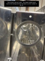
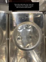
I'm still in the process of assessing my options for LCP that have been assembled. Has anyone else noticed that symmetrical ribs have been stamped both burn side out and burn side in? The cracks are noticeable with the scorch marks inside, are they less 'acceptable' than those stamped the other way? Pictures attached...
 

Attachments

  • Outie.jpg
    Outie.jpg
    292.5 KB · Views: 149
  • Outie-reverse-side.jpg
    Outie-reverse-side.jpg
    289.6 KB · Views: 134
  • Innie.jpg
    Innie.jpg
    343.3 KB · Views: 151
  • Innie-reverse-side.jpg
    Innie-reverse-side.jpg
    321.4 KB · Views: 135
Revised/updated Engineering Assessment Document

Vans posted an update today of their Engineering Assessment Document pertaining to the testing and analysis they are doing to understand the impact of laser-cut parts on airframe integrity.

The update contains exactly the additional information I was hoping for when I started this thread. Although it is not a comprehensive data document that shows the actual results of all the parameters they tested (grain direction, position of dimple crack relative to load, etc.) it does present the key take-aways that I was hoping for.

The added contents are:
1) a fairly detailed description of the nature of the test specimens and the range of variables explored
2) a description of the accelerated testing process and what constitutes 'end of test'.
3) An example result of one of the tests.

The example test specimen shows that when a riveted assembly is tested to fatigue failure, which takes the equivalent of many many airframe lifetimes, the fatigue crack does not originate from the edge of a dimple. Even more important for the present issue, in the presence of a pre-existing dimple crack, that crack does not propagate -- the failure occurs elsewhere. This is a key result that everyone should take note of.

Another test that bears emphasis was in the original document, not updated. The idea of residual strength testing. This represents a test of an essentially impossible what-if scenario. They basically cut up all the internal ribs inside the wing, as if every rib had cracked all the way through from the wing skin joint to the lightening holes, on both upper and lower surfaces, in multiple places. THEN they tested the wing and found that the wing still meets the limit load criteria!
 
Just a quick question related to the photo of cracked dimple on page 2 of the updated document. Would that crack be visible to the naked eye? If not, what kind of equipment would be required to see / detect such cracks?
 
They basically cut up all the internal ribs inside the wing, as if every rib had cracked all the way through from the wing skin joint to the lightening holes, on both upper and lower surfaces, in multiple places. THEN they tested the wing and found that the wing still meets the limit load criteria!

This is the kind of warm fuzzy feeling we engineers want to have but rarely achieved in our real jobs. I feel better about my wings even if it doesn't have the LCP. Even if I accidentally slip the rivet gun and messed up a few rivets, the wings still have a lot of safety margin.
 
Last edited:
Where can I find this document?

Dave

HI David,

On Vans website, scroll over the menu choice along the top that says "community" and then click on the "news" selection. There is a headline section about "information about possible cracking of LCP parts" and at the end of that paragraph, a symbol that looks like this: [...] in red.
Click on that and the document opens.

There are probably other paths to the document as well, but that is how I got to it.
 
I'm still in the process of assessing my options for LCP that have been assembled. Has anyone else noticed that symmetrical ribs have been stamped both burn side out and burn side in? The cracks are noticeable with the scorch marks inside, are they less 'acceptable' than those stamped the other way? Pictures attached...

I don't see anything concerning in any of these pictures. Well, except for the lack of primer. KIDDING!
 
Vans posted an update today of their Engineering Assessment Document pertaining to the testing and analysis they are doing to understand the impact of laser-cut parts on airframe integrity.

The update contains exactly the additional information I was hoping for when I started this thread. Although it is not a comprehensive data document that shows the actual results of all the parameters they tested (grain direction, position of dimple crack relative to load, etc.) it does present the key take-aways that I was hoping for.

The added contents are:
1) a fairly detailed description of the nature of the test specimens and the range of variables explored
2) a description of the accelerated testing process and what constitutes 'end of test'.
3) An example result of one of the tests.

The example test specimen shows that when a riveted assembly is tested to fatigue failure, which takes the equivalent of many many airframe lifetimes, the fatigue crack does not originate from the edge of a dimple. Even more important for the present issue, in the presence of a pre-existing dimple crack, that crack does not propagate -- the failure occurs elsewhere. This is a key result that everyone should take note of.

Another test that bears emphasis was in the original document, not updated. The idea of residual strength testing. This represents a test of an essentially impossible what-if scenario. They basically cut up all the internal ribs inside the wing, as if every rib had cracked all the way through from the wing skin joint to the lightening holes, on both upper and lower surfaces, in multiple places. THEN they tested the wing and found that the wing still meets the limit load criteria!

Respectfully, they tested a wing, from an RV-10, then made a blanket determination across the fleet. I'm not sure I share your admiration for the process.

Unless I'm misreading the document?

Also, I can't tell from the picture, but did the fatigue crack propagate to the hole (below and left of the identified LC crack)? I would imagine that that if aligned with the prevailing stresses, that would accelerate crack formation.

I'm happy to see a little more data, but there must be comprehensive analysis available in order for Vans to make their recommendations. Why not make it more widely available?
 
Last edited:
Back
Top