What's new
Van's Air Force

Don't miss anything! Register now for full access to the definitive RV support community.

360 Baffle dimensions

agent4573

Well Known Member
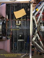
Does anyone have the measurements for the orange and green arrows? I'm going to build a box to layup a new plenum and want to get the forward/aft and left/right dimensions right. I would go measure mine, but I already have a plenum and don't have the front baffle piece installed. Thanks. Pic was shamelessly stolen from another post here on VAF and is a from a 320. Not sure if its the same as the 360, but I'm looking for the 360 dimensions.
 

Attachments

  • baffling.jpg
    baffling.jpg
    362.1 KB · Views: 97
Last edited:
Baffle dimensions on my current 360; width 30 3/4", length 17"
Width should be same on any 360 as is width of valve cover attach points.
Length will be unique to each different engine as the builder determines where the front baffle plates are attached, based on fit to their engine & cowling inlets.
 
Last edited:
Length will be unique to each different engine as the builder determines where the front baffle plates are attached, based on fit to their engine & cowling inlets.

Interesting. I'll go study the drawing a bit more to see how much wiggle room I have there. Thanks for the info.
 
Alternate plenum layup

Interesting. I'll go study the drawing a bit more to see how much wiggle room I have there. Thanks for the info.

I have an alternate option but you do need the forward plate attached.
Install the top cowl
Reach inside with a sharpie on a stick and draw a line on the top cowl where the baffles would touch if they were longer.
Remove the cowl.
Apply packing tape to the cowl covering the area defined by the marking is a few inches of border.
Wax the tape.
Apply two layers of saturated cloth then peel ply. Cure.
If you want a carbon fiber plenum, use one layer of carbon fiber.
While waiting for the cure, apply packing tape to the inside and outside of the baffles from the edge down about 2". Apy masking everywhere else to protect. Wax it.
Lay a 2" wide strip of two layers of saturated cloth over each edge. Half inside. Half outside.
Draw lines on the top cowl layup where the baffle lines show through.
Now take the layup from the top cowl and lay it on top of the wet cloth strips on the baffles.
Lift the portion of the strips on the outside and press them in place against the top. Doesn't have to be perfect. As long as some of the strip sticks and cures. It will look like the "eve" on a house. Fully cure.
Pop the plenum off. Apply flox and cloth to the inside vertex all the way around. Cure.
Now you can cut off the "eve".
What you end up with is a plenum exactly matching the contour of the cowl and fitting the inside shape of the baffles.
The rest is just adding layers inside to strengthen it.
If it's a carbon fiber plenum, use black tinted epoxy to saturate the additional layers of fiberglass added inside.
The exterior is finished with a fill of clear epoxy like 105 & 207.
Probably not the expert method, but it works and it fits.
 
Hey wirejock, I appreciate the input. I've read up on doing something similar to that and have decided against it. It's a great method but there's a few factors that have made me consider an alternative path. Im done using point fasteners for the plenum and want to go with piano hinge along the sides and back for a 100% sealed surface. The back of my motor is really crowded along the top as well, so getting screws into the vertical back baffle is really hard. The ones I have now are strategically placed to allow tool access, but in reality I need to double the numbers of screws back there to prevent leaks. In order to get the piano hinge to follow the contour along the top of the baffles, I'll have to add some 90 degree aluminum angle and lay the hinge flat instead of vertical.

The other major consideration is, like you said, the front baffle has to be installed to make it work. That means I have to pull my old baffling off and get all the new stuff mocked up on the engine before I start my layup. I don't want to take the plane down for weeks while I'm making the new plenum, so having a properly dimensioned desktop box let's me build and perfect everything in the garage then transplant it into the plane in hopefully less than a weekend. I should be able to pull the plenum this weekend and see where it fits the best in order to get a decent spacing on it though. That's probably the best way to get the box to be the right size.
 
Last edited:
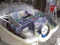
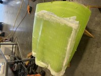
Similar to Wirejock, I used the cowling as a mold to layup the plenum. 4 ply of 8oz is mostly transparent. You can then trim to fit pretty easily. After it’s trimmed you can body work then add a few layers of carbon for stiffness and aesthetics.

150A0079-908B-4035-8DC1-6946E5B629BE.jpg
 
Last edited:
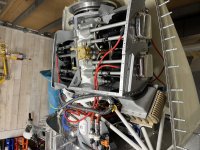
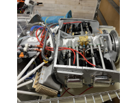
Attaching the plenum to the baffle is accomplished via flanges and k1100 nutplates riveted to the baffles. The complex baffle sheet to inlet cylinder geometry will get layed up over a foam plug after everything is locked into place.

Ugh I give up trying to rotate these images.
77B8F794-AFDC-47DF-9350-C3B9C326BDAE.jpg
 
Last edited:
What thickness aluminum did you use to make your flanges? Did the front bracket just need to be fluted to make that bend or did you have to cut some relief into it?
 
Plenum

Attaching the plenum to the baffle is accomplished via flanges and k1100 nutplates riveted to the baffles. The complex baffle sheet to inlet cylinder geometry will get layed up over a foam plug after everything is locked into place.

Ugh I give up trying to rotate these images.
View attachment 46576

I see. Interesting approach. I see how a mock up would work.
Keep us posted.
 
Believe it or not the flanges were cut off of scrap RV-9 fuselage seat ribs. Vans shipped a few random rv-9 parts with my -7 kit that were supposed to be interchangeable. This was just before they switched to lcp’s. The seat ribs are not interchangeable. The difference was imperceptible until i was attaching the bottom fuse skin.

The forward flange required removal of a small relief wedge, otherwise everything was fluted into shape. I think a gasket or bed of rtv between the plenum and flange will be required for an air tight seal. I’ll update the forum with results after it’s finished.
 
Last edited:
Baffle dimensions on my current 360; width 30 3/4", length 17"
Width should be same on any 360 as is width of valve cover attach points.
Length will be unique to each different engine as the builder determines where the front baffle plates are attached, based on fit to their engine & cowling inlets.

Curious about the front to back distance. There's 2 brackets that are included that set the front to rear distance. I can't find out where the wiggle room is that lets you change the distance in that direction.

I measured mine and a buddy's width as well today and came up with 30.5" instead of 30.75". My maintenance manual only gives total width from valve cover to valve cover. Anyone have an official diagram of the width of the engine from flange to flange without valve covers?
 

Attachments

  • Untitled.png
    Untitled.png
    2.3 MB · Views: 22
Last edited:
Did you get it yet?

I measured all these dimensions to build my plenum mold. Attached is what I think you asked. I did confirm that it matches the print I got from Lycoming, and a bunch of plenums made do fit like a glove.

I assume the James plenum still does not cool well?

Edit: The length is plane to plane, not the angled distance.


Baffle 5A.jpg
 
Last edited:
I measured all these dimensions to build my plenum mold. Attached is what I think you asked. I did confirm that it matches the print I got from Lycoming, and a bunch of plenums made do fit like a glove.

I assume the James plenum still does not cool well?

Edit: The length is plane to plane, not the angled distance.


View attachment 46626

Thanks Bill. What print did you get from Lycoming? Your front baffle plate is very different than whats depicted in OP-40, and the measurement is about 2 inches shorter than everything I've been able to measure. The brackets you used look custom, and it appears the front baffle is moved rearward by an entire case bolt, leaving the propeller oil line outside of the baffle area instead of inside of it like Van's has shown in OP-40. Was this done just to increase the length of the round to square transitions?


My current plenum cools ok, but I've changed enough on it now that it's time to just redo it. When we took off for Oshkosh is was hot on the west coast and we were planning on going over the Sierra Nevada's at 15.5k. In order to keep the temps down in long climbs, I cruise-climb around 120-130 KIAS, which isn't an issue below 10k. Above 10k fully loaded on a hot day, we ran out of climb way before 15.5 at 130 indicated. So I'm hoping a redo of the baffling lets me keep temperatures under control in a 90-100 KIAS climb. Once in cruise and LOP, I'm in the 360C CHT range, which isn't bad, but it could be a lot better. Mixture set for max power at 75% cruise ROP and I'm hovering right around 400 CHT. So while I can keep CHT under 400 at all times now with some pilot procedures, it would be nice to find ~20C or 20 KIAS and never have to worry about it again.
 
I’m curious what you’re changing on your second plenum. Is there anything to look out for when building one from scratch? This is my first plenum and I haven’t gotten too scientific about it. My goal is a nice smooth transition with moderate ramp angles from the round inlets to the box shaped cylinder area.
 
I’m curious what you’re changing on your second plenum. Is there anything to look out for when building one from scratch? This is my first plenum and I haven’t gotten too scientific about it. My goal is a nice smooth transition with moderate ramp angles from the round inlets to the box shaped cylinder area.

To start with, my current transitions are junk. I think I also installed my plenum way too close to the engine. My gap is only about 1 inch between the push rod tubes and the plenum. I don't think I left enough room for the air to slow down and increase in pressure. So this time around I'm going to focus on really smooth transitions and an ever increasing height as the plenum goes backwards.
 
Baffle dimensions on my current 360; width 30 3/4", length 17"
Width should be same on any 360 as is width of valve cover attach points.
Length will be unique to each different engine as the builder determines where the front baffle plates are attached, based on fit to their engine & cowling inlets.

My apologies on dimensions, I now remember I pieced this engine's baffles together from an old Vans 320 baffle kit (remember when components weren't pre-punched & directions were hand drawings!..), copying & or modifying parts where necessary.

I see from the thread direction that you are determining your forms dimensions on YOUR measurements, as it should be.
 
Thanks Bill. What print did you get from Lycoming? Your front baffle plate is very different than whats depicted in OP-40, and the measurement is about 2 inches shorter than everything I've been able to measure. The brackets you used look custom, and it appears the front baffle is moved rearward by an entire case bolt, leaving the propeller oil line outside of the baffle area instead of inside of it like Van's has shown in OP-40. Was this done just to increase the length of the round to square transitions?


My current plenum cools ok, but I've changed enough on it now that it's time to just redo it. When we took off for Oshkosh is was hot on the west coast and we were planning on going over the Sierra Nevada's at 15.5k. In order to keep the temps down in long climbs, I cruise-climb around 120-130 KIAS, which isn't an issue below 10k. Above 10k fully loaded on a hot day, we ran out of climb way before 15.5 at 130 indicated. So I'm hoping a redo of the baffling lets me keep temperatures under control in a 90-100 KIAS climb. Once in cruise and LOP, I'm in the 360C CHT range, which isn't bad, but it could be a lot better. Mixture set for max power at 75% cruise ROP and I'm hovering right around 400 CHT. So while I can keep CHT under 400 at all times now with some pilot procedures, it would be nice to find ~20C or 20 KIAS and never have to worry about it again.

Yes, that is my selected location to give more room for a diffuser to work, the only reason. Well maybe the only reason, I wanted some attachment to the case to handle vertical pressure loads. There is a vague recollection (possibly imaginary) that the Vans location was not that solidly attached. Also, my cover is separate from the diffusers allowing the cover to be removed.

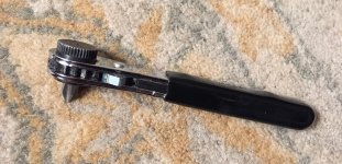
My fasteners on the back of the aft baffle are a bit difficult to get to, I use a very short bit (cut off ) in a flat hex ratchet that works ( the only thing) in smaller head room back there. I use #6 screws and as short as possible to lessen the manual time. The remainder are all handled with a DeWalt screw gun.
IMG_1778.jpg
 
To start with, my current transitions are junk. I think I also installed my plenum way too close to the engine. My gap is only about 1 inch between the push rod tubes and the plenum. I don't think I left enough room for the air to slow down and increase in pressure. So this time around I'm going to focus on really smooth transitions and an ever increasing height as the plenum goes backwards.

Keeping it 1/2" from the cowl is about right, it provides enough height at the front of the heads to keep that restriction point to a minimum. Gently shaping and expanding from the inlets back to the head face is another aid in diffusion. The hump behind the prop is pretty useless for the airflow, but may allow clearance internally for what ever the fuel and ignition have left in there. I calculated the expansion from the inlets and tried to make the area transitions smooth. After a year of design, experiments and research I froze the design, but I think if another was pursued I would reduce the prop hump in the middle as much as clearance would allow.

The James plenum was a copy of a successful RV4 design which is why it is so close/low to the engine on top. It has lousy inlet diffusers and is restricted at the head faces. It also uses a lot of axial length in constant area in the inlet nozzles and then connection flange. DanH did away with that and effectively utilized that length. If one keeps the machined inlets then the compromise remains. That area needs a new design.

To address the earlier question - I got an engine installation drawing, all the views and dimensions and locations of items needed to engineer an installation. Also got the specifications sheet for the M1B.

At least the Vans baffles have a straight aft wall and square corners to the heads.
 
Last edited:
Back
Top