What's new
Van's Air Force

Don't miss anything! Register now for full access to the definitive RV support community.

A Few Tip-Up questions

Rockyjs

Well Known Member
Patron
I have finished for now wrestling with the forward canopy frame (call it a draw) and I'm working on the side and aft canopy frame. I have a few questions.

Is there any reason structurally why I can't trim off the forward canopy skin ears? If I'm going to glass the front of the canopy around to the side, I would simply place a keeper in the glass for the canopy. I believe Dan C. said that he would cut the ears off if he did another tipper.

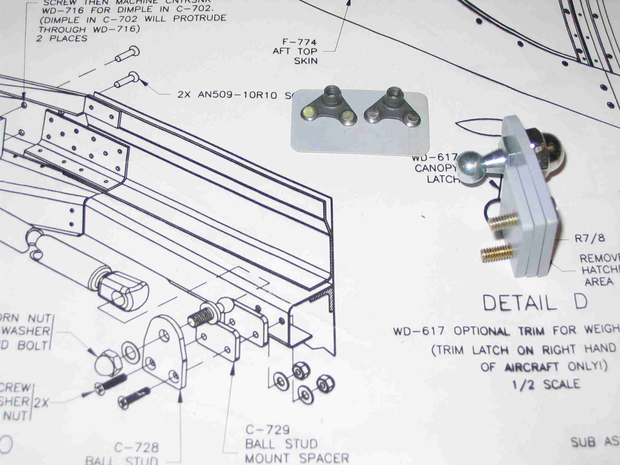
The other issue I have is locating the pivot block on the canopy frame for the strut. I have two pre-punched skin holes that would interfere with the block placement as depicted in the plans. I don't believe I could get rivets in on both of these. Is there any reason that the aluminum pivot block shouldn't be located adjacent to the 613 splice plate? I believe this is a stronger point on the frame. This position should also augment the strut operation by yielding a slightly better leverage point.

Thanks
 
Rockyjs said:
Is there any reason structurally why I can't trim off the forward canopy skin ears? If I'm going to glass the front of the canopy around to the side, I would simply place a keeper in the glass for the canopy. I believe Dan C. said that he would cut the ears off if he did another tipper.
I did cut 'em off. Glassed over that area.
 
I left my tabs on. Seemed to work OK for me. Variants in construction and parts plays many factors in how things fit. I doubt removing the tabs affects the integrity of the frame, especially since you glass that all in..

I attached some shots of the strut pivot location on my plane. Hope this helps.

Roberta

canopyfitsuu0.jpg


canopyframe7hi7.jpg


canopyframe9xb7.jpg
 
Last edited:
Simple way to install the gas struts

Here is a simple way to install the gas struts.

http://www.experimentalaero.com/gas-strut-install.jpg

Cut a piece of scrap material and drilled two hole for mounting to the gas strut mounting blocks. The hole spacing is 1/16 over what van's recommended to take into account the manufactures tolerances of the gas spring (the plans had the spacing at nominal conditions). Use spacers to place the mounting blocks on the cockpit rails. Simply drill the screw holes. Repeated the process on both sides. Perfect outcome.

I did relocate the canopy strut mounting block (aft if I recall) to clear the two offending skin rivets.

Cut the ears off the forward skin. I waisted a lot of time trying to make them work out but in the end I removed them. Wished I had removed them from the start. For those who were successful keeping them on hats off to you.
 
Last edited by a moderator:
Dan, Roberta and Paul,
Thanks for the advice and pictures. I think I have it sorted out now. Does anyone have any pros and cons to mounting the fuselage pivot directly to the inboard side rail instead of on the doghouse bracket? Doing a search, I saw a picture of the strut mounted this way looked like a clean install.
 
I would think the siderail without the extra material bolted to it might be weak. It would also change the geometry and may not raise the canopy properly. Mine has been working great as Van's designed it. Another point: the length and geometry that Van's determined between the pivot points allows the strut to reach "near" full compression prior to the canopy closing. That final motion to close now extends the strut, effectively going over center, and the strut actually pushes the canopy shut for the last few inches. That way the canopy strut is not under full compression when latched. It works really well that way. The geometry is really critical to get the mechanism to work this way and to get the canopy fully open.

Roberta
 
Plus, how are you going to tighten the nut if it's behind the rail? Access back there is poor at best.
 
I'd leave the ears on if you can. They help form a continuous "top cap" for the side rail beam as it joins the forward frame. (The glass is fine but I'm always wary of bonded aluminum joints over the long term.)

I'd also fit the strut blocks where the plans recommend and drill new skin holes if necessary. Mind you my aircraft is pre-prepunched so I'm used to laying ouy and drilling holes to suit:)

Jim Sharkey
RV6 - Getting there!
 
Mount per plans!!

Rockyjs said:
Does anyone have any pros and cons to mounting the fuselage pivot directly to the inboard side rail instead of on the doghouse bracket? Doing a search, I saw a picture of the strut mounted this way looked like a clean install.

You need to make sure you have the right gap (distance) from the side rail to the strut ball mount. The body of the gas strut comes very close to the canopy frame when opening or closing the canopy. Mine is built per plans and I only have about a 1/16" gap between the canopy frame and the gas strut. If there isn't enough gap the gas strut will rub against the canopy frame, scratching off paint from both the frame and the gas strut.

Also make yourself a nutplate plate to ease the installation of the two screws for the gas strut rail mount.
 
Pmerems said:
Also make yourself a nutplate plate to ease the installation of the two screws for the gas strut rail mount.
Definitely a great 20:20 hindsight TIP!
 
Good Tips thanks. What about the distance between the pivot balls? The plans on DWG 49 have a minimum of 9 11/16" and the directions that came with the struts 10 1/4". Maybe I should measure the struts compressed and add about 3/8" (clearance) to this distance for the pivots spacing.

I assume that the "nutplate plate" would be two #8 nutplates on a piece of backer material match drilled using the ball stud mount screw spacing and placed behind the rail to accept the number 8 screws of the mount assembly?
 
Rockyjs said:
I assume that the "nutplate plate" would be two #8 nutplates on a piece of backer material match drilled using the ball stud mount screw spacing and placed behind the rail to accept the number 8 screws of the mount assembly?
Zactamundo. Use a piece of .032" with two nutplates in it -- instead of the nuts. Once both screws are started the plate serves as anti-rotation for the nutplates. No wrench required at all (getting a wrench back there is a minor pain at best), just tighten the screws from the easily accessible side & you're done.
 
Question: I've just finished making the wedges and am ready to drill them to the 713 wplice plate and the 716. The instructions say to take some scrap angle and clamp it to the bottom of the side of the rail and 716 to keep things straight.

I'm not following that ,as there are clecos on the side to hold splice plate in place , which precludes any angle being clamped there.

Anyone got a picture of what the instructions are talking about?
 
Bob Collins said:
What's a nutplate plate?
Check out this picture of the nutplate plate I made:


BTW, I cut those ears off and glassed over them. Check out my fuselage page and scroll down to the 12/3/06 & 12/8/06 entries.
 
Last edited:
N941WR said:
Check out this picture of the nutplate plate I made:


BTW, I cut those ears off and glassed over them. Check out my fuselage page and scroll down to the 12/3/06 & 12/8/06 entries.

I just installed nut plates directly on the inside of the deck rail using blind rivets. I dimpled for teh flush heads using Avery pop rivet gun dimpling dies.
Cheap, light and simple.
Jim Sharkey
 
Back
Top