You can get dacron polyester fabric from just about any local fab store in various weights. When we were building the two Cozy MKIV's at my house, I would even find it on clearance once in a while in the Walmart fabric center for .99 cents a yard. If you use a fabric with a dyed pattern, it will sometimes bleed through though and leave the pattern on your fiberglass part!

Van's Air Force
You are using an out of date browser. It may not display this or other websites correctly.
You should upgrade or use an alternative browser.
You should upgrade or use an alternative browser.
Tip: Fiberglass Fabrication
- Thread starter DanH
- Start date

MonkeyWrench
Member
Hi guys. One more question for you all. The term micro bubbles is used a lot. It seems like a generic term. It looks like it just means small glass bubbles. Is it safe to say that the 3M GLASS BUBBLES on ACS is the same thing as the generic micro bubbles?
3M GLASS BUBBLES
https://www.aircraftspruce.com/catalog/cmpages/bubbles.php
I'll be using West Systems (I did see Dan's original note on the pumping of the product). Will probably just poor it.
However, West Systems has all kinds of speciality 400 series fillers.
https://www.aircraftspruce.com/catalog/pdf/WestSystemManual.pdf
It seems that you can obtain the same level of finish as the West Systems 400 series fillers by using micro bubbles and varying the amount micro bubbles you add.
Thanks all!
Sorry Rich, missed your question.
Microballoons are generally available in glass (white) and phenolic (dark red). They are the basic ingredient in almost all lightweight fillers.
The West line of fillers incorporate additional ingredients, most of which are equally common (for example, talc, styrene, and wood fiber). Obviously different blends impart different properties. In my opinion, those property changes are of little value to homebuilders. For sure the West blends are very expensive compared to stocking the shop with ordinary glass micro, flox, and cabosil.
czechsix
Well Known Member
How many plies to glass empennage tips to aluminum?
For those who have glassed in their empennage tip fairings to get the seamless look, how many plies and what ply weight worked well? I like the look but want to minimize weight, and this isn't structural....but a single layer of very thin glass might crack over time due to vibration and different thermal expansion rates between the fiberglass tip fairing and adjacent aluminum surface. So I'm particularly interested to hear from those who have been flying for a while (what has -- or hasn't -- held up over time?).
Thanks,
For those who have glassed in their empennage tip fairings to get the seamless look, how many plies and what ply weight worked well?
No fabric plies at all. Tips bonded with Hysol, riveted wet, gaps filled with micro. Still doing fine at 875 hours.
czechsix
Well Known Member
No fabric plies at all. Tips bonded with Hysol, riveted wet, gaps filled with micro. Still doing fine at 875 hours.
Wow, that's amazing...I'm really surprised that you haven't seen any hairline cracks show up where the micro meets the edge of the aluminum skin!
Thanks,
Wow, that's amazing...I'm really surprised that you haven't seen any hairline cracks show up where the micro meets the edge of the aluminum skin!
So I'm told. It's an experiment, and may explode any minute.
So, more than a decade ago, why did I think it would work? Here's reality. The tips are cheap polyester glass. The coefficient of thermal expansion is about 14 microinches per inch per degree F. The coefficient for aluminum is typically around 13. There is no significant thermal expansion difference to drive cracking, thus I assumed cracking was merely a function of poor component fixation.
The polyester glass is inside the aluminum flange, and evenly bonded (i.e. evenly stressed), not fastened at individual points. I could have drilled out the pop rivets after the Hysol cured.
Check back in another 800 hours. I'll keep the crow in the freezer.
Last edited:
MS19087
Well Known Member
Which Hysol is recommended?
Dan - There are many Hysol variants out there- what is the recommended Hysol product for this application?
Thanks!
No fabric plies at all. Tips bonded with Hysol, riveted wet, gaps filled with micro. Still doing fine at 875 hours.
Dan - There are many Hysol variants out there- what is the recommended Hysol product for this application?
Thanks!
Dan - There are many Hysol variants out there- what is the recommended Hysol product for this application?Thanks!
9430 is fine.
czechsix
Well Known Member
9430 is fine.
Did you use the Hysol 9430 for any particular attributes or was it just what you had handy? I have some West System epoxy that I've used for some of the fairing work...any reason it would not be equally suitable for bonding the fairing to the aluminum?
Did you use the Hysol 9430 for any particular attributes or was it just what you had handy? I have some West System epoxy that I've used for some of the fairing work...any reason it would not be equally suitable for bonding the fairing to the aluminum?
I had it handy; it's a good general use structural adhesive.
Compared to laminating formulations, epoxies intended as structural adhesive often spec lower in modulus, tensile, shear, and Shore hardness. Although "lower" as a desirable trait is non-intuitive, it is a trade-off in return for higher peel strength, the classic Achilles heel. Think "less brittle, more rubbery".
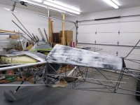
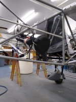
Not an RV, but some may find the techniques transferable, and I'd love to see a bit more custom stuff in our fleet. These parts feature carbon's primary structural attribute, stiffness. They're for an orphan Rans S-9 which wandered into my shop.
The standard canopy is not tall enough for me, and it's ugly as sin.

I decided to convert to an open cockpit sportster, a fun flying adjunct to the RV-8. At the regular 08A Sunday sunset meeting, one of the group sort of dared me to build it all in lightweight carbon, which was actually sensible, unlike most of our beer meeting ideas. The current plan will make both sections removable with just a few fasteners, quickly exposing the entire interior of the fuselage for inspection and maintenance.
Really stiff parts at lowest weight require that the top and bottom fiber elements be moved apart with a core element. Here I went with 1/8" honeycomb, similar to a Vans cowl. The best matrix application (the epoxy) would be to use pre-preg, but I was far too lazy to build the necessary oven, pre-preg is expensive, and cheap foam forms can't be baked anyway. The game was to see what I could do with a typical home shop wet layup, vacuum bagged.
First thing was to make two foam forms. They required a nice surface finish, in particular the turtledeck, because I want to leave the inside carbon pattern exposed. For whatever reason, folks just love the look.
Methods are just like the smaller parts in previous posts...shape foam, seal it, give it a smooth finish, wax, PVA, and do the layups.


Clean up, then lay out and cut all the materials.

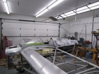
Now for the fun part. Very rapidly, drape the first ply of 5.7 oz twill on the form, wet it out, then drape the honeycomb. Wet out the top ply of twill between plastic sheet to keep epoxy ratio reasonable, peel one side of the plastic, and drape it over the honeycomb. Add a perforated release ply, and a bleeder ply, then slide the whole thing into a big bag (furniture storage bags are huge), seal it, and apply vacuum.

The raw turtledeck shell, untrimmed, weighs a bit over two pounds. It would be a little lighter if made from prepreg, as there is some excess epoxy with the wet layup. However, the wetness means the interior finish is attractive with no other work. It is very stiff, and not being structural, more than strong enough to mount on the airplane with no interior ribs. It's just a big fairing. I will put a headrest bulkhead in the cockpit end.
The cockpit cover was made in a similar fashion, but with more carbon (5.7 twill and 12oz plain weave on the inside, 12 oz plain and a top sheet of 9 oz glass on the outside). It must support the windshield, and stand up to abuse when the pilot gets in and out.
Plenty more detail work to do, but here are the basic shells. I have two windshields, one the forward end of a broken RV-4 bubble, and this one, the aft end of an RV-8 bubble I found in the shop attic. I have not decided between them yet, but it should be a cute airplane either way. More later.

The standard canopy is not tall enough for me, and it's ugly as sin.
I decided to convert to an open cockpit sportster, a fun flying adjunct to the RV-8. At the regular 08A Sunday sunset meeting, one of the group sort of dared me to build it all in lightweight carbon, which was actually sensible, unlike most of our beer meeting ideas. The current plan will make both sections removable with just a few fasteners, quickly exposing the entire interior of the fuselage for inspection and maintenance.
Really stiff parts at lowest weight require that the top and bottom fiber elements be moved apart with a core element. Here I went with 1/8" honeycomb, similar to a Vans cowl. The best matrix application (the epoxy) would be to use pre-preg, but I was far too lazy to build the necessary oven, pre-preg is expensive, and cheap foam forms can't be baked anyway. The game was to see what I could do with a typical home shop wet layup, vacuum bagged.
First thing was to make two foam forms. They required a nice surface finish, in particular the turtledeck, because I want to leave the inside carbon pattern exposed. For whatever reason, folks just love the look.
Methods are just like the smaller parts in previous posts...shape foam, seal it, give it a smooth finish, wax, PVA, and do the layups.
Clean up, then lay out and cut all the materials.
Now for the fun part. Very rapidly, drape the first ply of 5.7 oz twill on the form, wet it out, then drape the honeycomb. Wet out the top ply of twill between plastic sheet to keep epoxy ratio reasonable, peel one side of the plastic, and drape it over the honeycomb. Add a perforated release ply, and a bleeder ply, then slide the whole thing into a big bag (furniture storage bags are huge), seal it, and apply vacuum.
The raw turtledeck shell, untrimmed, weighs a bit over two pounds. It would be a little lighter if made from prepreg, as there is some excess epoxy with the wet layup. However, the wetness means the interior finish is attractive with no other work. It is very stiff, and not being structural, more than strong enough to mount on the airplane with no interior ribs. It's just a big fairing. I will put a headrest bulkhead in the cockpit end.
The cockpit cover was made in a similar fashion, but with more carbon (5.7 twill and 12oz plain weave on the inside, 12 oz plain and a top sheet of 9 oz glass on the outside). It must support the windshield, and stand up to abuse when the pilot gets in and out.
Plenty more detail work to do, but here are the basic shells. I have two windshields, one the forward end of a broken RV-4 bubble, and this one, the aft end of an RV-8 bubble I found in the shop attic. I have not decided between them yet, but it should be a cute airplane either way. More later.
So, Dan, is your vacuum pump regulated? What depression are you using? My pump would suck the foam down flat
Yep, limited to around 20", controlled leak when necessary. Seems to be close to the limit for pink foam. My crappy little junkyard pump rarely pulls more than 22" or so anyway.
Last edited:
Mike S
Senior Curmudgeon
. They're for an orphan Rans S-9 which wandered into my shop.
Wandered in-------right
BillL
Well Known Member
Yep, limited to around 20", controlled leak when necessary. Seems to be close to the limit for pink foam. My crappy little junkyard pump rarely pulls more than 22" or so anyway.
I have to get a different pump and try this on my next vacuum bag project. The actual vacuum pump i use for infusion can not tolerate excess air with a leak.
Thanks!!
So, Dan, is your vacuum pump regulated? What depression are you using? My pump would suck the foam down flat
Bill, a little follow up. Added a 5oz twill carbon top ply after bonding in the forward bulkhead and a bunch of other little details, then loaded on a batch of micro and blocked it flat. Note the faint stripe pattern. Tells me the pump did suck the foam in a little bit, even at 20" or so. I could drop suction to 10", and it would just suck it in half as much. When I think about it, it can't be any other way, as all materials exhibit strain behavior. And as usual, you make me think
.
Attachments
Redneck engineering doesn't always require fancy test equipment.
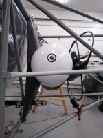
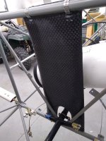
This a a carbon fiber mount for a BRS parachute canister. The "official" mounting method means kluging lengths of steel tube into the airframe, and bolting the canister to it using a big steel bracket from BRS. Just the steel bracket alone is 1.25 lbs. Figured there had to be a better way.
It's a hollow shell, mostly 12k plain weave carbon, bagged on a foam form then closed at the back later in the assembly. Not going to describe the whole process here, although I hope you find it inspirational. It did save weight as desired. The whole assembly, with the BRS-supplied steel straps, is only a fuzz over 2 lbs.
The redneck part was making sure it was strong enough...see the last photo. The entire canister, rocket, and mounting system is just over 20 lbs. If a 220 lb redneck can dance around on the mounted canister without a problem, it has to be good for at least 11G
.
Attachments
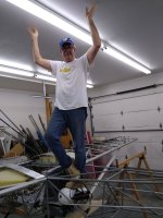
Yoga
Looks more like yoga to me Dan! Looking forward to your thread on how to use your rag and tube aircraft as a makeshift yoga mat!... If a 220 lb redneck can dance around on the mounted canister without a problem, it has to be good for at least 11G
BillL
Well Known Member
Bill, a little follow up. Added a 5oz twill carbon top ply after bonding in the forward bulkhead and a bunch of other little details, then loaded on a batch of micro and blocked it flat. Note the faint stripe pattern. Tells me the pump did suck the foam in a little bit, even at 20" or so. I could drop suction to 10", and it would just suck it in half as much. When I think about it, it can't be any other way, as all materials exhibit strain behavior. And as usual, you make me think
.
I rescued a worn out pump from our pond aeration system and it pulls about 20" (a new pump does 25") and could do less with a controlled "leak" valve.
On your layup, it is faint so not so bad, but it was probably stiffer along the micro bond lines, hardly a solution for that. But good to know what to expect.
David Paule
Well Known Member
It's handy to include a leak valve, pressure gauge and a sump. Never know what debris might come back.
Interesting, the discussion about the pressures. Here in Colorado I can't get much about 20" anyway.
Dave
Interesting, the discussion about the pressures. Here in Colorado I can't get much about 20" anyway.
Dave
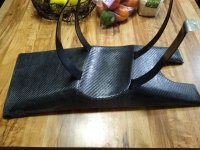
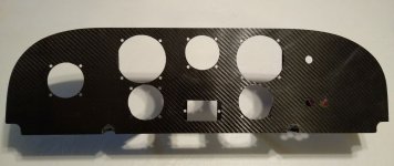
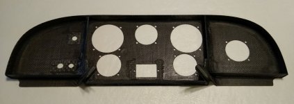
Carbon panel. There is still a place for basic steam gauges in very light VFR projects.
Face is one ply of 6K twill and two plain weave, with a perimeter flange and two upright ribs. The flange and ribs are simply strips cut from a bagged 3-ply 12K flat layup, attached to the face panel with a flox fillet. A little black epoxy dye makes the flox blend in nicely.
The half-rounds are four plies of twill formed on a waxed aluminum tube from the scrap bin. They seat the panel on fuselage tubes. One screw and nutplate will attach the top of the panel to the cockpit cover shell.
Hope it gives you crazy ideas about making something custom for your RV
.
Attachments
Laird
Well Known Member
Hi Dan,
It was built back in the dark ages before digital photos(1998 or so). Not sure where the prints are at this point.
Basically I build a plug from foam to get the shape I wanted, glassed it and finished it up as nicely as I could. Then I pulled a mold off the plug using about 3/16" thick worth of epoxy/glass. I cleaned up the new mold a bit and added .063 alum inserts to provide the recess for the inserts that would be used later.
This was before carbon became "reasonable"(?) in cost, so it's all glass. 1 ply of 3 oz crowfoot (style 120), then 4 plys of Rutan 7725. It was just a wet layup without bagging it.
Now that I think about it there may a little bit of 12K carbon uni in the lower flange that might have followed me home from work....
It was a fun project and it's the thing my RV-6 gets complemented on the most.
You've done a great service to the collective putting all this info into a thread. Hopefully it'll lead people to try to be creative.
Laird
No fabric plies at all. Tips bonded with Hysol, riveted wet, gaps filled with micro. Still doing fine at 875 hours.
Revisiting this old post ...
Did you just fill the gap between tip and aluminum, or fill the pulled rivet heads as well?
Trying to decide how to attach / finish the empennage tips.
Thanks
Thomas
Did you just fill the gap between tip and aluminum, or fill the pulled rivet heads as well?
3/32 CS pulled rivets in dimples, filled.
scsmith
Well Known Member
I have to get a different pump and try this on my next vacuum bag project. The actual vacuum pump i use for infusion can not tolerate excess air with a leak.
Thanks!!
We find that whenever laying up over foam molds, we limit the vacuum to about 12" to prevent compressing/distorting the mold. Yes the foam is an elastic material and will compress some at any vacuum. But it seems to 'yield' somewhere above 12" and the distortion becomes much more evident.
On the vacuum pump I put a tee fitting, and then in one leg of the tee, put a needle-valve and a gauge that allows me to set vacuum fairly precisely. My cheap ($30 on ebay) medical diaphragm pump won't pull more than 18" or so anyway, and that works well for small parts.
For big parts, like glider wings, we have a big vacuum pump mounted on top of a surplus water heater tank that provides a large capacity vacuum reservoir. That pump can pull about 24" at the shop altitude of 4000 ft. I'm sure it would pull much harder at sea level.
scsmith
Well Known Member
So I'm told. It's an experiment, and may explode any minute.
So, more than a decade ago, why did I think it would work? Here's reality. The tips are cheap polyester glass. The coefficient of thermal expansion is about 14 microinches per inch per degree F. The coefficient for aluminum is typically around 13. There is no significant thermal expansion difference to drive cracking, thus I assumed cracking was merely a function of poor component fixation.
The polyester glass is inside the aluminum flange, and evenly bonded (i.e. evenly stressed), not fastened at individual points. I could have drilled out the pop rivets after the Hysol cured.
Check back in another 800 hours. I'll keep the crow in the freezer.
I did the same thing, but didn't even use 9430. Just thickened epoxy with flock and cabosil. Filled edges with micro. I was prepared for it to develop cracks if it wanted to, but 11 years and 650 hrs and no cracks.
Here's a fine example of dumb.
Bill previously mentioned his pump would suck foam flat. I said I was pulling about 20 inches. I'm not.
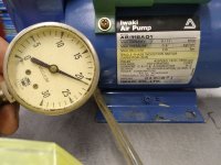
I've been using this pump about 15 years, when it was removed from a medical machine at a friend's large recycling yard. The gauge came with it. There is no notation of units on the gauge face, and all these years I have assumed the marked range of 0 to 30 was inches Hg. Turns out it is actually centimeters Hg, an odd unit, or torr, or mmHg when read as indication x 10.
The obvious clue is the pump label (duh!). If I ever looked at it, it didn't dawn on me to convert torr to familiar units. Certainly explains why I'm not sucking foam forms down to pancakes.
TIME OUT
This may all be a coincidence of terms. Bill says 210 torr may be an absolute value, 210 more than zero. If so the gauge really is indicating 21" below atmospheric, i.e. 29.92 adjusted for elevation. I'll check it with an altimeter or something tomorrow.
UPDATE
There's an old (bad) joke which goes something like "I thought I was wrong, but I was wrong".
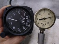
Dug out old altimeter and hooked it up in parallel with the USG dial gauge. Photos attached. Bill nailed it. The 210 Torr pump rating is indeed absolute, not depression, meaning it is rated to pull down to 210 mmHg above absolute zero. The USG dial, on the other hand, indicates depression below atmospheric.
I originally set 300 feet as my local altitude above MSL. After releasing the vacuum it settled on 350. No big surprise I guess. That poor old altimeter has never seen 30K+ with anything I’ve owned, and I don't know if it has ever been checked. It's also hard to say if the USG gauge is real accurate given its unknown pedigree.
The big picture is close enough; I have indeed been squeezing the layups at something in excess of 20" Hg deltaP, or roughly 10 lbs per sq inch.
-
Bill previously mentioned his pump would suck foam flat. I said I was pulling about 20 inches. I'm not.
I've been using this pump about 15 years, when it was removed from a medical machine at a friend's large recycling yard. The gauge came with it. There is no notation of units on the gauge face, and all these years I have assumed the marked range of 0 to 30 was inches Hg. Turns out it is actually centimeters Hg, an odd unit, or torr, or mmHg when read as indication x 10.
The obvious clue is the pump label (duh!). If I ever looked at it, it didn't dawn on me to convert torr to familiar units. Certainly explains why I'm not sucking foam forms down to pancakes.
TIME OUT
This may all be a coincidence of terms. Bill says 210 torr may be an absolute value, 210 more than zero. If so the gauge really is indicating 21" below atmospheric, i.e. 29.92 adjusted for elevation. I'll check it with an altimeter or something tomorrow.
UPDATE
There's an old (bad) joke which goes something like "I thought I was wrong, but I was wrong".
Dug out old altimeter and hooked it up in parallel with the USG dial gauge. Photos attached. Bill nailed it. The 210 Torr pump rating is indeed absolute, not depression, meaning it is rated to pull down to 210 mmHg above absolute zero. The USG dial, on the other hand, indicates depression below atmospheric.
I originally set 300 feet as my local altitude above MSL. After releasing the vacuum it settled on 350. No big surprise I guess. That poor old altimeter has never seen 30K+ with anything I’ve owned, and I don't know if it has ever been checked. It's also hard to say if the USG gauge is real accurate given its unknown pedigree.
The big picture is close enough; I have indeed been squeezing the layups at something in excess of 20" Hg deltaP, or roughly 10 lbs per sq inch.
-
Attachments
I have a lab vacuum pump which will pull to 1 X 10E-004 Torr or very near a complete vacuum. I have been making molds from pink insulation foam and pulling full vacuum without a noticeable change in dimensions. However none of the parts I am making are that dimensionally critical. BTW, I am at 300 ft msl, so get pretty high pressures from the atmosphere.
I did have concerns about this and before making the molds, I vacuum bagged a 2” thick block of foam that I cut into a dimensioned block. I applied the vacuum and then measured the block with the vacuum applied. It did change some and the corners tended to round, but nothing major.
I did have concerns about this and before making the molds, I vacuum bagged a 2” thick block of foam that I cut into a dimensioned block. I applied the vacuum and then measured the block with the vacuum applied. It did change some and the corners tended to round, but nothing major.
Last edited:
Easy Composites video tutorials
Probably a bit strong to call these tutorials, but I found the videos very instructive.
https://www.youtube.com/user/easycompositestv/featured
Probably a bit strong to call these tutorials, but I found the videos very instructive.
https://www.youtube.com/user/easycompositestv/featured
Airbox replacement for a Bower can with broken reed petals, on an RV-8. The usual pink foam form, epoxy sealed, waxed, PVA, do the layups. Variation here is doing the whole job on the lathe....shaping the foam, the layups, sanding, the works. Just set a spidle in the foam with wet micro, and use it to spin the form.
Not an optimum solution, but it should keep the rocks out for now.
Roughing with a hand saw:

Shaped, epoxy skin, sanded, waxed, ready the spray PVA:

After cure, the shelled foam peels out of the 4 ply layup like a bad sunburn:

Tried a new trick. The layup got an epoxy wipe followed by sanding, then it was sprayed with an epoxy primer; the first shot of primer lets you see any remaining imperfections. Surface was good enough for this engine component, but there were a half dozen random pinholes on the outside and a few hundred on the inside. Gave it a wipe, inside and out, with Akzo Nobel 28C1, the one shot pinhole filler, Seemed to work just fine on the primered surfaces. Me like, because it's real fast compared to chasing them out of a sealed surface with a two-part putty. The inner, non-sealed surface was a straightforward use for the 28C1; scrub on, let dry, scrub off the excess leaving the filler in the pinholes.
You might ask, why not just use the 28C1 on the outside right from the start? Well, it does nothing to hide weave or improve surface contour. The epoxy shell does both.


Not an optimum solution, but it should keep the rocks out for now.
Roughing with a hand saw:
Shaped, epoxy skin, sanded, waxed, ready the spray PVA:
After cure, the shelled foam peels out of the 4 ply layup like a bad sunburn:
Tried a new trick. The layup got an epoxy wipe followed by sanding, then it was sprayed with an epoxy primer; the first shot of primer lets you see any remaining imperfections. Surface was good enough for this engine component, but there were a half dozen random pinholes on the outside and a few hundred on the inside. Gave it a wipe, inside and out, with Akzo Nobel 28C1, the one shot pinhole filler, Seemed to work just fine on the primered surfaces. Me like, because it's real fast compared to chasing them out of a sealed surface with a two-part putty. The inner, non-sealed surface was a straightforward use for the 28C1; scrub on, let dry, scrub off the excess leaving the filler in the pinholes.
You might ask, why not just use the 28C1 on the outside right from the start? Well, it does nothing to hide weave or improve surface contour. The epoxy shell does both.
Last edited:
This was a quick job for a friend. I think we'll soon see market entires from two respected sources.Methinks there might be a market for these..........

