What's new
Van's Air Force

Don't miss anything! Register now for full access to the definitive RV support community.

Modifications that you have Made to your RV-12 after Certification? E-LSA Only!

It only seems counterintuitive to a non-pilot.

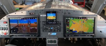
Most planes have the top of the switch labeled "DOWN", like you have it. I know it seems counter intuitive, but the way that I remember it is that pushing the top of the control stick causes the nose to go down.

The practice comes from years of "rolling" the trim wheel forward to produce nose down trim. As you roll the wheel forward, your thumb goes forward toward the panel. It's as if you are "rolling" the trim switch forward.
 
Tony
Howdy, I have the baggage mod kit ready to install. But just ordered the two pieces for the floor and the kind lady at vans said that?s all that is coming. So, how do I mod the floor ? Do I make mounting flanges to screw the two floor pieces in to or is there something else to order from vans??? Thank you, Doug in IL
 
Baggage floor mod fixtures

Tony Howdy, I have the baggage mod kit ready to install. But just ordered the two pieces for the floor and the kind lady at vans said that?s all that is coming. So, how do I mod the floor ? Do I make mounting flanges to screw the two floor pieces in to or is there something else to order from vans??? Thank you, Doug in IL

I am in the middle of an annual and have taken this opportunity of complete the mod to the baggage bulkhead and rear floor inspection panel that has been pioneered by others to allow inspection access without having to remove the fuel tank. Will also be doing the fuel tank reinforcement SB and installing a Moeller gauge on top while the tank is opened. Gad, this annual is getting to be a lot of work!
CTT4706-M.jpg

CTT4702-M.jpg

CTT4703-M.jpg


And this is the access with the covers off:
CTT4708-M.jpg


Many thanks to those who have gone before on this. Life should be a bit easier now. I hope to not take the tank out from now on except for cause.

The only issue I see is that Van's has never indicated whether these panels are structural or not. If they are, the mod may be a case of junior engineering a good design. If they find me face down in the trees somewhere with the tail cone a half mile from the wreck, you will know what happened and it will be all my fault and not Van's ;).

Tony
 
Hi Doug,

I don't think you need anything else. The two floor pieces should screw right to the original nut plates, no mounting flanges should be necessary.

Just understand that is an old post of mine and those floor pieces in my pictures were made by me BEFORE Van's changed their design to two floor pieces, so I have never seen the floor pieces that you will be getting.

Best luck, it should go easy.
 
Canon Plugs for Nav lights

I had the old screw head and prong set up for Nav lights and stall warning. Always had issues with poor connectivity so I installed a quick disconnect canon plug for both wings using about 16" of wiring encased in a protective sheath. All I do now is pull the wings out about a foot and disconnect the plugs, works great...That's what I wished they'd done designing it in the first place.
 
Exchanging Voltage Regulator

Before my Ducati VR is going to die, I thought it might be good to be prepared for. So, I bought the Silent Hektik VR at the Aero fair in Friederichshafen for 120?.
My voltage regulator is located under the avionic shelf on the right side, as per former KAI.
To be on the safe side, I installed a 2.8x2.8" PC fan on the cooling fins. The air flow will be from the passenger room upwards to the fins. The fan will be connected in parallel to the other 2 fans on the avionic shelf. (powered when master switch is on)


2mukz.jpg

34otzeo.jpg

9ao7dd.jpg

9iqovk.jpg


I hope my battery will like it :)
 
Neat arrangement Chris. I've just bought the F4122 regulator as the Ducati is electrically noisy, also the EarthX ETX680 battery as I want to move my C of G aft a bit. Hope to get them installed in the next couple of weeks. I'll copy the integrated fan mount - easier than moving the regulator back to the engine bay and installing Vans NACA duct.
 
Modifications

I like your location and setup.

My VR was already in the engine area so I copied another person from the Vans Airforce and moved it to the left out of the airstream from the radiator and then put a blast tube to it from the airstream to the radiator. I have a thermal strip on it and when I change the oil, I will learn how hot it is getting.

IMG-4608.jpg
[/url][/IMG]
IMG-4612.jpg
[/url][/IMG]
IMG-4614.jpg
[/url][/IMG]
IMG-4615.jpg
[/url][/IMG]

I changed the oil today, 5/24/2019 and the thermal strip indicated that 135F is the highest temperature that the VR got to.
 
Last edited:
Drag reduction with fairings, RV-12

Comparing airspeed and fuel burn vs. engine RPM before installing wheel fairings and then with, and then adding the nose wheel strut fairings, I was shocked by the significant improvement resulting from the latter. It caused me to speculate about the exhaust pipe which is also directly behind the propeller. Could a V-cross section fin behind the pipe could be beneficial in drag reduction, and maybe in reducing exhaust gas stain on the belly? Has anyone done anything in this area? I would like to hear about such work if it has no ill effects. At least it is fun to think about such things!

Norm T
Bought ELSA RV-12 flying, great little airplane!
Had Grumman Cheetah for 20 years prior
 
adding the nose wheel strut fairings, I was shocked by the significant improvement resulting from the latter.

How shocked were you? This can't add significant airspeed. Nose strut is very small and airspeed in low 100 knots doesn't gain very much from little bits of aerodynamic cleanup.
 
Actually it has been stated by Vans that the nose wheel strut has more drag than you would think! Expect an increase in 3 to 4 knots with the fairing on.;)
 
Jim,perhaps pleased, not shocked, would have been what I should have said. Thanks for sharing your opinion. Perhaps "significant" depends on your point of view. My evaluation was run on pretty much standard days, not same day, about 60 degrees F, 30"hg, AP straight and level, 3000' msl, 2800 agl, pilot only, maybe half tank fuel. Steady state at 5000 RPM: 100kts/no fairings; 105 kts/ wheel fairings, 110 kts/whl and strut fairings. I saw 120 kts at 5300 RPM, scary at 5800! I saw climb rates of 1000 fpm. All values my scanned readings, approximate but indicative, satisfied my purposes. Test by others will be different, I don't care, I like mine, may not be repeatable, evaluation was for my benefit and curiosity. I am not the builder, it was flying before my purchase. I like it! I really like it a lot! (On another thought, why do people have wheel pants on J-3 Cubs?) Have Fun, Jim.
Norm
 
On another thought, why do people have wheel pants on J-3 Cubs?

I can speak with a fair amount of authority about J-3's having owned one for 23 years and some 1100 flying hours. The only thing wheel pants do on a Cub is keep mud from flinging onto the bottom of the wing. Makes a real racket when clumps of mud start hitting fabric wing like a big bass drum...
 
Comparing airspeed and fuel burn vs. engine RPM before installing wheel fairings and then with, and then adding the nose wheel strut fairings, I was shocked by the significant improvement resulting from the latter. It caused me to speculate about the exhaust pipe which is also directly behind the propeller. Could a V-cross section fin behind the pipe could be beneficial in drag reduction, and maybe in reducing exhaust gas stain on the belly? Has anyone done anything in this area? I would like to hear about such work if it has no ill effects. At least it is fun to think about such things!

Norm T
Bought ELSA RV-12 flying, great little airplane!
Had Grumman Cheetah for 20 years prior

Do you have any pictures you could post up on the nose wheel strut fairing?
 
Thanks, guys! 5 kt's is 5 kts.

5 KPH is a lot ? almost 5% of cruise speed. I don't think I see that kind of improvement with all three pressure-recovery wheel fairings. RV-12 is not a fast machine that would benefit from a lot of aerodynamic cleanup.

Nose strut is a round tube which is bad for aerodynamic drag. But strut is short ~ 30? and mounted almost 45 deg to normal airflow.
 
Main gear fairings?

I have read of only one person trying to manufacture and mount a set of main landing gear fairings - believe that they use RV-8 lg fairings. Anyone else tried this idea out. Results? I'd expect a few more knots gained. Might reduce drag enough to get 120K at lower engine speed???
 
Jim,perhaps pleased, not shocked, would have been what I should have said. Thanks for sharing your opinion. Perhaps "significant" depends on your point of view. My evaluation was run on pretty much standard days, not same day, about 60 degrees F, 30"hg, AP straight and level, 3000' msl, 2800 agl, pilot only, maybe half tank fuel. Steady state at 5000 RPM: 100kts/no fairings; 105 kts/ wheel fairings, 110 kts/whl and strut fairings. I saw 120 kts at 5300 RPM, scary at 5800! I saw climb rates of 1000 fpm. All values my scanned readings, approximate but indicative, satisfied my purposes. Test by others will be different, I don't care, I like mine, may not be repeatable, evaluation was for my benefit and curiosity. I am not the builder, it was flying before my purchase. I like it! I really like it a lot! (On another thought, why do people have wheel pants on J-3 Cubs?) Have Fun, Jim.
Norm

Bolded, for statistical purposes, as real world results, under standard ATM conditions.
 
I have read of only one person trying to manufacture and mount a set of main landing gear fairings - believe that they use RV-8 lg fairings. Anyone else tried this idea out. Results? I'd expect a few more knots gained. Might reduce drag enough to get 120K at lower engine speed???

I've fitted RV-8 MGL fairings, and I know of others that have too. I doubt that they add more than 2-3 kts, but they look good.
 
Friend of mine with a gorgeous RV-12 has RV-8 gear leg fairings on his. They look amazingly good, but he also says he only picked up a knot or two. I have a set of fairings in my garage, but haven't gotten around to putting them on yet. Mostly because I'll have to fabricate my own upper and lower intersection fairings too, and the only chance I get to do that kind of stuff is in the dead of winter when it's waaaaay too cold for fiberglass work.
 
Friend of mine with a gorgeous RV-12 has RV-8 gear leg fairings on his. They look amazingly good, but he also says he only picked up a knot or two. I have a set of fairings in my garage, but haven't gotten around to putting them on yet. Mostly because I'll have to fabricate my own upper and lower intersection fairings too, and the only chance I get to do that kind of stuff is in the dead of winter when it's waaaaay too cold for fiberglass work.

I added those gear fairings as well. I was actually mostly interested in the upper intersection fairings in an attempt to reduce the "breeze" between the seats from back to front. I had upper intersection fairings, leg fairings and lower intersection fairings at the wheel fairings. I got my intersection fairings from Cleaveland Tools.

Didn't seem to affect the "breeze" and didn't add any measurable speed over the wheel fairings alone. I ended up removing them ...
 
One person Lower Cowl Holder

152fj7p.jpg


I may have posted this some time back, but was thinking about it today after I used it. I hook the heavy wire on the lowest hinge loop of the upper hinge, and you can see how I install it on the lower cowl ( I do bend the end a bit to keep in place ). It holds the lower cowl so you can get the oil cooler into position before pulling the lower cowl up and putting hinge pin in. Makes it much easier for one person.
 
Bolded, for statistical purposes, as real world results, under standard ATM conditions.

Thanks NinerBikes! I thought my results were interesting, but didn't expect critics. I will try not offer input again. My fairings are Van's standard option which I installed after purchasing and flying the 12. I appreciate your positive attitude, that is helpful.
 
I added those gear fairings as well. I was actually mostly interested in the upper intersection fairings in an attempt to reduce the "breeze" between the seats from back to front. I had upper intersection fairings, leg fairings and lower intersection fairings at the wheel fairings. I got my intersection fairings from Cleaveland Tools.

Didn't seem to affect the "breeze" and didn't add any measurable speed over the wheel fairings alone. I ended up removing them ...

Do you think that breeze helps keep the C0 level down by pressurizing the cockpit?
 
Do you think that breeze helps keep the C0 level down by pressurizing the cockpit?

I have no idea. All I know is that draft is very welcome down here in Florida in the summer :) and very unwelcome up north in December when it's sub-zero :(
 
Update on the effectiveness of the relocation of the Ducatti Regulator.
My relocated regulator has now 150 hours and going. The previous one failed at 100 hours on Hobbs.
After many failures of the Ducatti Voltage Rectifier/Regulator due to overheating VANS decided to relocate it inside the cockpit to improve the cooling. I decided that a better option was to relocate it inside the cooling tunnel. Here are in a few pictures the steps I took to achieve the relocation:

The components I used, an Al angle 2X2 1/8" thick with one side cut to 1"wide and a counterplate also 1" wide:

100_3785s.jpg


Cuts in the fiberglass of the tunnel:

100_3787s.jpg


Regulator secured on the angle:

100_3786s.jpg


Regulator installed inside the lower cowl's tunnel:

100_3788s.jpg


Lower Cowl in place with Regulator connected including a ground cable:

100_3789s.jpg


The ground cable goes to the battery housing:

100_3790s.jpg


As I decided to leave the initial connector untouched, I connected the extension I made to reach the tunnel with spade connectors but I had to secure the spade connectors with tie-wraps or risk a damaging disconnection of the alternator. On the picture you can see the stand-by Regulator located at the initial location on the firewall. In case of failure of the active located in the tunnel this standby unit can be switched into active by disconnecting the failed unit and reconnecting the standby.

100_3791s.jpg
 
SILENT HEKTIK INSTALL COWL RAIN CAP

MY SOLUTION TO RAIN AND MY NEW SILENT HEKTIK VR INSTALLATION IS ATTACHED
https://cliseproperties.box.com/s/wq9m35vnz5xutdw15fp8yglwe2g5ie4f[/IMG
[url]https://cliseproperties.box.com/s/lob5ur71n94m2pib1s348l6tia2414pn[/url]
[url]https://cliseproperties.box.com/s/g9xp6n7n1i4r0w5aizbr1lsxkxbl06x8[/url]
 
Last edited:
CO detector

Just installed a new Aithre Shield EX 2.0 Behind-the-Panel Carbon Monoxide Detector. Works great and looks great easy install. Integrates into the G3X touch via the GEA-24 50 or 37 Sub-D connector.

oHz.jpg


oHI.jpg
 
To get through it , I had to add some paragraphs to the aux tank recipe Interesting. Hmm. Maybe a 12.
r

... Edited - minor typos, added paras. -ron

Let's start with the 6 gallon tank first. You are going to have to rivet two brackets to the floor of the baggage compartment for the 2 inch nylon strap to go through to hold the fuel tank in place. Put them far enough apart so the tank won't rub on them when in place. Just use some thick scrap aluminum left over from your build to make them.

Next you need to vent the tank to the outside air so it won't expand or collapse. Take the swivel air fitting and install it in the filler cap of the tank. The fuel tank in the web link I provided has a vent in the fuel cap you will have to remove and you may have to drill and tap it for the swivel air fitting. Then you need to screw on a male Seasense Chrysler/Force Connector. The thread on the male fitting should screw into the swivel air fitting. You could probably leave the swivel air fitting off if you want but I liked its mobility.

Now attach the nylon freezer line to the female Seasense Chrysler/Force Connector. You may need to use a larger piece of tubing to put on the barb of the connector and then push the nylon tubing inside of it. What ever works for you. Then run the nylon tubing down through the hole in the center of the main spar, where the wiring come through, to the center inspection plate on the bottom of the airplane.

In the center of this inspection plate install a long shank 3/16 inch rivet with the nylon tubing on it like the static ports in the plane. Pop the mandrel out before you attach the other end of the tubing to the female connector on the cap. Don't worry about the ethanol factor in this line, it won't have fuel in it except for the occasional slosh when completely full on a bumpy ride and it won't be under pressure either. Also leave a little slack in the nylon line for future removal of the inspection plate.

Next attach male Seasense Chrysler/Force Connector to the fuel pickup on top of the fuel tank. The threads should match, 1/4 inch NPT. Then connect a female Seasense Chrysler/Force Connector to the end of the 3/8 ID fuel line you can probably picked up at your local auto parts with one of the hose clamps. Remember that this tubing will not be under pressure either but should be ethanol compatible . Then connect this tubing to the barb connector screwed onto the in side of the facet fuel pump. You will need to attach the two Jeggs barbed AN fittings onto the Facet pump.

Next attach another length of 3/8 ID fuel tubing on the out side barb of the Facet pump. Run this fuel tubing to the right side of the aircraft up past the ELT toward the fuel tank neck. About half way along the top of the airplane fuel tank install the Moeller inline fuel filter using a couple more hose clamps. Then add the last female Seasense Chrysler/Force Connector to the 3/8 fuel tubing.

Next mark the airplane fuel tank filler next where you want to install the last male Seasense Chrysler/Force Connector and then remove it and drill a hole onto the filler neck to install the connector. When you insert the male Seasense Chrysler/Force connector into the filler neck you are going to need a nut to install on the 1/4 NPT thread to hold it in place. Which nut fits this? Would you believe a AN bulkhead fitting nut. An AN6 as shown in the Jeggs web site link will work. It will be a little loose so don't over tighten or you will strip it. Put some proseal on the threads and smooth some around the hole then tighten the fitting on to the nut just slightly past hand tight. Remember this won't be under pressure either, you want it to hold firm but not leak.

I mounted my Facet fuel pump inside the main spar using the same bolt that holds the fuel tank in place as you can see in the pics with this post. To do this you will have to cut the bottom mounting tab off so the other tab will line up correctly. Also if you were on a cross country flight and your in plane electric pump failed you now would have a temporary spare. I put 3/4 inch heat shrink over my hose clamps to give it a more pleasing look as you can see in the pictures. Next you will need to wire up your pump to the power port plug with the on/off switch. This will go into the power port when you want to use the aux tank.

Couple things to remember. You have to burn off 6 gallons of fuel in your main tank befor you transfer your aux tank fuel. It takes about 20 mins to transfer 6 gallons. Hey it's only a 3.5-4PSI fuel pump. You don't want to leave the pump running dry for too long. Think about setting a count down timer on your Dynon to keep track of your transfer. Also the best part is you can look over you right shoulder and view the fuel filter just beyond the Moeller gage and see the fuel running through it and know for sure when you are done transferring fuel.

I think I've cover most of what guys need to know to build and install their own tank. I reserve the right to have left something out or maybe posted the wrong link to a wrong size part. If I have then when you build your Aux tank feel free to post the correction here like when we find a mistake with RV12 plans. Also this is a very simple setup for use in an experimental airplane that can be removed in 5 minutes. Also if you improve on the design the let us all know. If you don't feel safe using it then don't use it. Remember as PIC you make the call.

Maybe the Flightline guys can come up with a hose kit for a cleaner installation.

Pics to follow!
 
Oil Door opening spring mod

I normally leave my oil door open for cooling, one day the wind blew it closed and I missed that it was not latched on the preflight. Just as I was lifting off the door started flapping, I had enough runway left and landed so no harm was done but it made me think.
I have added a spring to the door to hold it open. The pictures are self-explanatory. I wound the spring 4 coils out of .045 music wire. The spool is aluminum and I used a longer bolt to put it all together.

50146150327_83aa0940d2_c.jpg

The stock right side hinge.

50145367153_5346c2899c_c.jpg

Parts to do the mod, the spring and sleeve I made.

50145910641_7e28f38f0e_c.jpg

finished with spring in place.

50145910721_91c8564007_c.jpg
 
Last edited:
I installed a 1/4" Drive Type Grease Fitting on the nose fork pivot bushing. I used 1/16” thru drill and then ¼” drill x ¼” deep counterbore.
-
 

Attachments

  • Screen Shot 2021-01-13 at 6.37.01 PM.png
    Screen Shot 2021-01-13 at 6.37.01 PM.png
    3 MB · Views: 469
I upgraded my grips to Tosten CS-8 grips. I did it during the conditional inspection so I had everything open saving some time. I estimate about 2 days additional work for the mechanical and electrical rewiring.

This grip added selection of radio channels, flip flop, elevator trim, and autopilot, plus trigger PTT. My OEM trim on the dash was changed to a on/off switch that can disable the right seat stick grip functions. The OEM autopilot CWS button was changed to a toggle for the fuel pump, (it stays on during all phases of flight).

CS-8 installed.jpg
 
Added Garmin GPS 175 Navigator, Dynon D3 and several other items to panel

I completed some additions to my panel, primarily to provide GPS/IFR navigation capability. Not for "hard" IFR by any means, but to allow me to maintain currency and the ability to get out of places when ceilings are too low. Took opportunity to add a few more items at the same time. Summary video link, and photos below.

https://youtu.be/kpUzCfVtjW4

1. Relocated DYNON AP/Knobs panel to lower right panel to make room for GARMIN GPS 175 top center. Powered GARMIN unit by tapping into power plug circuit (wanted to use different fuse than the one for the Dynon GPS for redundancy) Simply mounted DYNON D3 battery powered backup attitude indicator beside the GARMIN unit on right side for redundancy. Passengers now have more to look at too.

Installed DYNON ARINC on top of glove compartment box inside avionics bay as this is needed to connect GARMIN unit to Skyview. Had SteinAir create wire harnesses which worked seamlessly.


2. Installed "go around" button for GARMIN added below AP disconnect. (will add placard)


3. Expanded plate and mounted GPS antenna to existing shelf in engine compartment for GARMIN WAAS antenna. Was concerned about proximity/possibly interference to existing DYNON 2020 antenna but initial testing OK.


4. Added RAM mount using doubler to bottom left avionics shelf for iPad


5. Added switch for power to facet fuel pump on upper left, above ignition switches. Read all the back and forth on it already in the forums. Wanted ability to turn off mechanical pump on ground when loading s/w without pulling fuse.


6. Added additional USB power plug on lower right side of panel for passenger and also to recharge DYNON D3 as needed.


Nice! I've considered similar. Is there any concern about 'power budget' with the 912ULS? Or any concerns on voltage regulator after install?

I'm interested in the mod for 2 reasons:
  1. Training to get my Instrument Rating
  2. Ability to do VERY light IFR
 
Nice! I've considered similar. Is there any concern about 'power budget' with the 912ULS? Or any concerns on voltage regulator after install?

[/LIST]

Power draw was a question for me too. Of the various Garmin navigators this one takes the least. The units with nav/com, FIS-B etc... capabilities clearly draw more. Trying to find reference but I understand the 175 takes about 2 amps, install calls for a 5 amp fuse, which is what the power plug circuit I tapped into has already. Limited testing to date, but it operated fine with two different USB chargers simultaneously connected, one for an iPad and the other on the Dynon D3. I will not plan to operate it that way but was curious. Impact on regulator to be monitored.
 
Last edited:
Added G5 with backup battery as a tertiary backup attitude indicator (primary, look out the window, secondary G3X, tertiary G5). Plumbed into pitot static system, so also provides secondary airspeed and VSI.

Completed painting
 

Attachments

  • IMG_1786.jpeg
    IMG_1786.jpeg
    227.6 KB · Views: 475
  • IMG_1927.jpeg
    IMG_1927.jpeg
    330.7 KB · Views: 398
I upgraded my grips to Tosten CS-8 grips. I did it during the conditional inspection so I had everything open saving some time. I estimate about 2 days additional work for the mechanical and electrical rewiring.

This grip added selection of radio channels, flip flop, elevator trim, and autopilot, plus trigger PTT. My OEM trim on the dash was changed to a on/off switch that can disable the right seat stick grip functions. The OEM autopilot CWS button was changed to a toggle for the fuel pump, (it stays on during all phases of flight).

View attachment 13361


Hi,
can you give me some information how you did it? Especially considering the wiring? I own a RV-12 ULS (still with the D180) and I am also thinking about adding the trim and AP disconnect to the yoke. However, Vans couldn't help me with it and now I am not sure how to approach the change. Do you have a wiring scheme you are willing to share?

Thanks!

Just small technicality... you don't have a yoke. RV-12 has side-by-side sticks.
 
Back
Top