wirejock
Well Known Member
Doubler
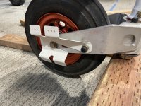
Sounds right. I do remember making a a larger doubler to allow the contactor to sit even to each other. Can't remember why. It made sense at the time. Found a photo.

Got it.
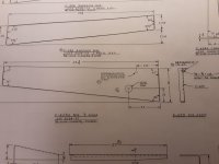
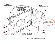
But I see another "gotcha" here: the firewall doubler from OP-32 reuses two of the holes on the firewall. Since it goes to the front of the firewall, the firewall (ideally) should not be dimpled in these two holes (and stiffener behind the firewall should not be counter-sinked). Right?
Sounds right. I do remember making a a larger doubler to allow the contactor to sit even to each other. Can't remember why. It made sense at the time. Found a photo.


 Luckily, I only drilled the gusset, not the longeron / engine mount, so I am just going to replace the part.