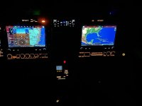
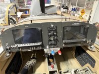
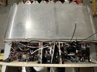
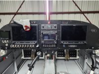
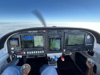
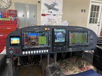
Below is post I made a couple days ago on the DeltaHawk thread on the RV14 page. Thought I would post it here as well since it is panel specific and may be of use for folks working on RV14 panels in general (not necessarily DeltaHawk specific panels)….
Post:
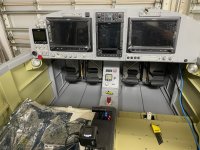
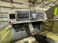
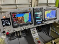
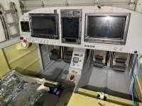
Here is the panel we will be using in the DeltaHawk RV14. There's a lot to unpack here, so look at the schematic and the panel rendering first and then the comments below should mostly make sense. Hopefully, I did this correctly and the pics have enough resolution - I was able to zoom in on features after posting.
Back Ground: The panel for the DeltaHawk project was originally built about two years ago by Aerotronics (Jason Smith’s outfit in Billings, Mt). He's done countless panels for Synergy Air in Eugene for RV builders - and, is almost exclusively used by the RV14 builders there. The panel was originally intended to be in my 'next' RV14 - which fortuitously became the test plane for DeltaHawk. The original design was a new iteration of the panel in my current RV14, with some minor modifications to allow a co-pilot to have more access/control over the avionics. The biggest change vs the old panel was the addition of a 7” G3X on the co-pilot side. Now, with the introduction of the DeltaHawk engine to the mix, there are a few more alterations.
Features - In General:
Sharp eyes may notice the additional real estate on the DeltaHawk panel vs a stock RV14 panel. It comes from two (2) sub-panels - to the left and right of the throttle area. Both lightly recessed (towards the firewall about an inch). This idea came from an RV7 built around 2000 by Mitchell Lock – long before he joined Van's and became their CEO (I purchased this RV from Mitch in 2003 and accumulated about 1000 hours on it before selling). I never found the lower panels to hamper clearance for my legs (I’m just shy of 6' tall), and the added real estate opened layout options for the upper panels. On the DeltaHawk panel most of the switches are located on the lower panels. There are also some circuit breakers - but most of the circuitry is routed through the VP-X electronic circuit breaker system (it didn’t have the capacity for all of the circuits in this panel).
The Panel is set up to allow two (2) pilots to share tasks, although it will function for a solo pilot just fine.
Avionics:
Full IFR Garmin Set-up:
GTN 750i
G3X (10” and 7")
Remote Audio panel, Remote Transponder, Remote Comm2 - all accessible thru the G3Xs (IMO the G3X interface is superior to the head mount for these items, and it frees up significant space on the panel for the TVs).
Auto-Pilot
Connexts - for bluetooth streaming
Additionally, the DH panel has two layers of redundancy. First, dual G3Xs allow for reversionary mode should one unit fail (much like having a G5). Secondly, there is accommodation for a Stratus/Sentry and iPad(s) running Foreflight. Should the whole panel go dark (unlikely, but one never knows) - one could navigate or manually shoot an emergency approach using the ADHRS generated from the Stratus/Sentry and displayed on the iPad. The iPad and the Stratus/Sentry have dedicated USB charging ports, but also have internal batteries so they will continue to operate for quite some time in the event of a power loss.
Specifics on the various sections of the panel:
Lower Panels:
No Mixture Control Knob. The DeltaHawk engine doesn't use one. It has only Throttle and Prop Controls.
Switches: Laid out generally in order of use (left to right). I will only cover the ones that may need some 'splainin'.
“EFIS” switch: Located to the far left since, with the Garmin, its good to power up the G3X asap, as all the engine gauges are displayed via its MFD. One would want this up and running before engine start and it takes about 30 seconds to power up.
“
Start" switch: Replaces the Keyed Ignition one sees in most Lycoming installations. Hold the switch 'down' to heat up the glow plug, then hold the switch 'up' to start the engine.
“Idle Gov” switch: This is particular to the DeltaHawk engine as compression ignition engines are difficult to control at idle. The Idle Governor works in conjunction with the fuel control unit. The idle governor, when turned on, will ensure the engine never operates below 1200 rpm. This needs to be on a pilot operated switch to shutdown the engine. (*simplified* shutdown procedures are to turn off idle gov and bring power lever to idle).
“
Fuel Pump” switch: This is located on the right sub-panel, a bit out of the way – as its function is primarily as a back-up to the engine's two (2) mechanically driven fuel pumps. The delivery fuel pump sends fuel from tanks at about ~50 psi to the high-pressure fuel pump. The high-pressure fuel pump sends the fuel at very high pressures to each injector. The electrical pump is a backup for the delivery fuel pump and is an FAA part 33 requirement. DH is still developing the fuel system procedures; typically, the boost pump is activated during start-up, then turned “off” at taxi commencement, and then remains in the 'off' state. The G3X is configured to indicate low fuel pressure. If this were to happen the boost pump should be turned “On”.
Emergency Engine Stop Control (pull cable): Required to allow for two (2) methods of shutdown. Typical shutdown is completed by switching “off” the Idle Gov and bringing the power lever to “idle”. Since this is a compression ignition engine, the secondary method of shutdown is to pull the Emergency Engine Stop. This cable will close off induction air, quickly shutting down the engine
.
Left Upper Panel:
iPhone: The schematic doesn’t show the details well, but we have an iPhone Max (on an articulating mount) to the left of the G3X. Again, personal preference. Having put the iPhone in about every conceivable place in the RV7 and the RV14, this seems to be one of the best options for readability and accessibility. A USB outlet is adjacent to the mount for charging the phone flight. Personally, I tend to use the full-sized iPad (on the right side of the panel) for navigation and other stuff, but its also handy to have the iPhone to access checklists (foreflight), checking weather along a route, and managing playlists (bluetoothed through the panel).
Cabin Heat: Heat is NOT supplied via a heat muff on the exhaust, instead it taps into heat from the coolant hoses. The heat system is located aft of the firewall (other than the coolant lines that supply hot coolant to the heat exchanger) and sits against the firewall above the exhaust tunnel.
The Cabin heat control cable controls the flow of coolant through the firewall. With it pulled, coolant will flow through the cabin heat exchanger (wouldn’t want a 200F heat exchanger sitting in the cabin on a hot day). There are air diverters/ducting to direct the heat towards pilot/copilot feets.
The control knob controls the speed of the fan to recirculate the air through the heat exchanger. This system eliminates the risk of CO and the need for the cabin heat doors.
Warning Lights: Probably all are self-explanatory except the "Idle Gov". This is to warn the pilot the Idle Gov is not engaged (once the engine warms up, it should be engaged for the entire flight). Idle Gov light will illuminate if the Idle Governor is not receiving power.
Center Upper Panel:
Overall, this area doesn't need much commentary. While the Comm2, Transponder, and Audio panel are all remote mounted (accessed thru the G3X), our preference is to have the actual panel head for the Auto-Pilot. Personally, I use the AP in probably 80% of my flying. Even when not in IMC, the AP is being used to hold altitude, climb/descend, steer with the heading knob, or follow a route in a flight plan. Hand-flying the plane is great, but on many flights its very enjoyable to set the AP, listen to some great music, and enjoy the amazing scenery! Having the AP head below the GTN works nicely as it enables easy back-and-forth with the Throttle/Mixture controls.
Right Upper Panel:
Mostly self-explanatory again. The dark matter on the right represents a full-sized iPad. It doesn't show that well on the schematic – especially in that with the mount we use, the iPad can be positioned in almost limitless orientations. I currently have this set-up in my RV14. It uses a MyGoFlight articulating mount - the iPad can be flat against the panel, rotated, tilted, or even extended over towards the pilot (useful when flying solo and one doesn’t want to strain to see/reach the iPad). A USB plug for in-flight charging is located next to the mount (behind the iPad). Also, behind the iPad is a glove box.
Astute observers who have not fallen asleep from my long-windedness, will note there are leading edge light controls above the 7" G3X and may wonder why these are necessary when the lighting switches on the lower left panel seem to cover all the bases. It’s for more lighting - especially when landing on a grass strip in the middle of Nowhere Mountains. The Aveo Zip tips are nice, but they lack a bit of forward lighting for this type of venue. So, we're wired up for an off-road set-up, but have yet to decide on which brand of lights use. Looking for something like "Elk Spotters 1000". We’ll be visiting all the light guys at Air Venture this year.
Few Random things:
Inogen Oxygen System. We will likely be using Windblade's Inogen O2 concentrator. I use this in my current 14 and love it. It’s to be ‘hard-wired’ and the unit will sit just below the throttle area (Van's has a slanted panel some folks use for circuit breakers down there – we’ve converted it to hold the Inogen Unit). No tanks to fill (!!!) - it literally concentrates O2 from air in the cabin and delivers it via a cannula to your nose. Its approved for use up to18'K msl (there are asterisks - talk to Tom at Windblade for info).
Control Sticks: We are using Tolsten. Been very happy with them in the past. Functions: PTT, CWS (control wheel steering), AP disconnect, Freq Swap, Flaps. Can’t recall, but I think we may have allowed for the leading-edge lights to be controlled by one of the little hidden buttons below the PTT switch.
Headsets: The plane is equipped to use both Lemo and traditional jacks for the headsets.
Last edited: Yesterday at 8:14 PM


