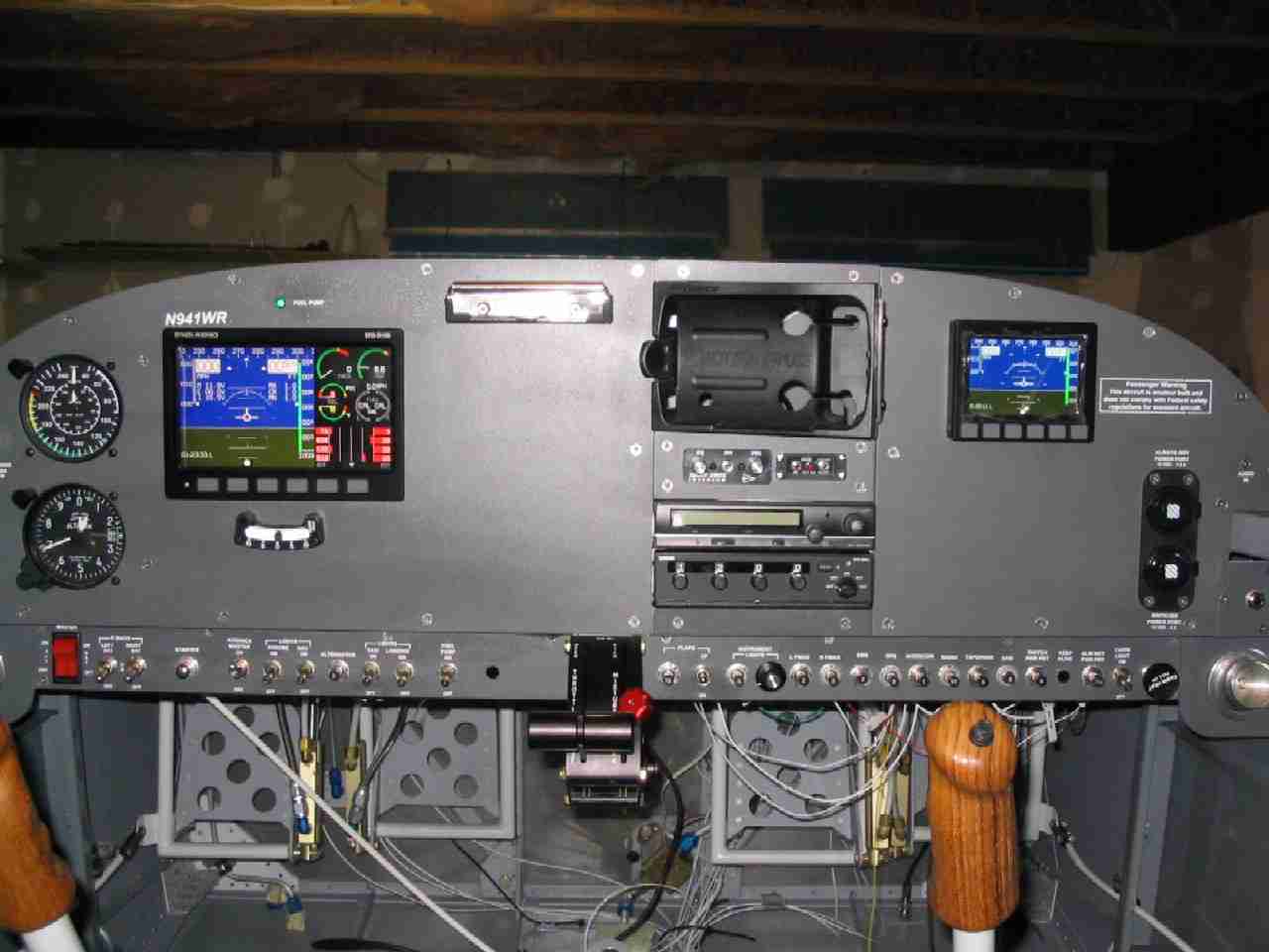
What's new
Van's Air Force

Don't miss anything! Register now for full access to the definitive RV support community.

Garmin 496 Connection

N941WR

Legacy Member
Could someone who has hard wired their 396 or 496 give me some pointers.

The manual isn't so clear, thus my confusion.

The wire connecter is labeled in the following manor:
Red: DC Input
Black Ground
White: Alarm
Brown: Voice (+)
Orange: Voice(-)
Yellow: Port 1 in
Blue: Port 1 out
Green: Port 2 in
Violet: Port 2 out

Red & Black - I have those down, not a big problem. One question, the positive (red) wire has a fuse on it. Since I am wiring this to a breaker, do I still need the fuse?

Alarm: Is this for a warning light or is it a warning tone?

Brown & Orange: Is this a voice warning, such as the terrain warning. Thus it sounds like it can be wired into my intercom.

Yellow & Blue: ?

Green & Violet: ?

My -9 will not have an autopilot (at this time) but it does have a Dynon D100.

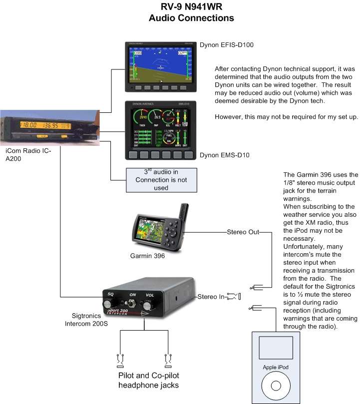
Here is a diagram of how I have my electronics wired:

This was drawn before I received the Garmin and I had no idea how that would connect into my system.

Also, how do you connect the XM radio into the system.

Thanks for the help!
 
gps 396 & 496

The garmin 396 & 496 has a plug for the audio (music) out put,
looks like a hole in your ipod for headphones, buy or build a plug
that is wired to your intercom input..

Red: DC Input = Aircraft Power (mine is on the dynon d-180 buss)

Black Ground = Common ground (share with the dynon ground per dynon)

White: Alarm = audio to intercom system, not totally sure of this one
audo or visual but I think this is correct and also the alarm will output
from the music plug also.. I think the visual is on the 496 screen

Brown: Voice (+) per garmin (only for auto and boating use)
Orange: Voice(-) " "

Yellow: Port 1 in = I am not using it (not sure what this is for) anyone ?

Blue: Port 1 out= to Autopilot

Green: Port 2 in= I am not using it see above

Violet: Port 2 out = serial buss see below the updated pin out
this one on mine will go to pin 19 on the 37 pin on my d-180 ,
if you only have the efis then its pin 22 on the 25 pin plug, see below

Depending on the number and types of Dynon units you own, you have several options for connecting a GPS unit and/or Garmin/Apollo SL30 to your Dynon system. The GPS can be used as a source for both the HSI and Fuel pages. The SL30 can be used as a VOR or localizer source for the HSI. If you wish to connect a GPS and/or SL30 to your Dynon system, read the section below which corresponds to your set of Dynon products.

To fully use the GPS-related features on your EFIS and/or EMS, your GPS must output the following NMEA sentences in its serial stream: $GPRMC, $GPRMB, $GPGGA, $GPBOD, and $GPAPB. All of these connection schemes assume that the external devices share a common ground with the Dynon product(s). If your GPS is battery powered, and not normally connected to aircraft ground, you must connect the ground pin on its serial output to a ground common to the EFIS or EMS that your GPS is connected to (e.g., pin 9 on the EFIS DB25, or pin 16 on the EMS DB37).

When a Dynon product is connected to a GPS, it will synchronize its Zulu clock to that output by the GPS.

If you own only an EFIS-D10A or EFIS-D100:

Hook the GPS or SL30 transmit line into pin 22. This is the same Serial RX line that is used for firmware updates. You'll need a way to disconnect this when you hook up a PC.

If you have both a GPS unit and an SL 30, you'll need to hook the two transmit lines to a switch and use this switch to decide which one you want displayed on the HSI. The HSI will auto-detect the switch being changed and will change modes automatically.

If you own an EMS-D10 or EMS-D120:

Hook the GPS transmit line into the EMS pin 19 on the D-37 connector. This is labeled "Fadec RX." This connection will give you range, MPG, etc. No point in hooking up an SL 30 since that only sources info for the HSI display which requires an EFIS. No need to break this connection when doing PC updates.

If you own an EMS AND an EFIS:

Hook the GPS or SL30 transmit line into the EMS pin 19 on the D-37 connector. This is labeled "Fadec RX." This will share the data between the EMS and EFIS and allow you to display an HSI on either product, as well as do EMS economy displays.

If you have a GPS and an SL 30, hook the GPS up as above. Hook the SL 30 to pin 22 on the EFIS. This will allow you to use the "NAVSRC" button on the HSI to flip between inputs. The only tradeoff here is that you can only display a GPS HSI on the EMS. You can see either the SL 30 or GPS on the EFIS. You'll need to disconnect the SL 30 from the EFIS when doing software updates.

Alternatley, you can use a switch into the EMS which will allow you to see both the SL 30 and GPS on both the EFIS and EMS, but you will only be able to see one at a time.

If you own a D180:
Hook the SL 30 unit to pin 22 on the EFIS (vertical D-25) and the GPS to pin 19 on the D-37. You can display either source on the HSI with the "NAVSRC" button. You'll need to disconnect the SL 30 from the EFIS when doing software updates.

If you own a D180 AND an EFIS:
Hook the SL 30 unit to pin 22 on the EFIS (vertical D-25) and the GPS to pin 19 on the D-37. You can display either source on the HSI with the "NAVSRC" button, and you can display either on the standlone EFIS as well. You'll need to disconnect the SL 30 from the EFIS when doing software updates.

hope this helps and is not too long..

Danny..
 
Last edited:
Bill:

According to Garmin Tech Support,the orange and brown wires are for voice output to the car speaker for use when navigating in your car. Don't hook up the voice output to your intercom; you'll likely do some damage. Normal audio output for terrain and XM Radio on the 396/496 is via the 1/8" audio plug on the back of the unit.
 
Agree, additional

Bill, The COM1 output is for serial GPS signal such as to an autopilot. On the 496, the COM2 is for the weather, according to Garmin when I checked this week. That pair should not be used. If you use COM1 you have to configure it. Go to Setup, Interface tab. If you select an NMEA option you can press Menu to go to advanced NMEA for further details. The 296 had a COM2 output configuration but the 496 doesn't because they took it for the WX. I think the documentation with the XM antenna gives more info on hook up for that (mini-USB, I think). The tag on the power cable gives detail on which wire goes where. Also, in case nobody said it already, you can drive multiple devices with the COM1 by forking the wire. It's not unusual to see three devices driven off that wire (blue on mine).
Call while I'm in the hangar if you need to go over any details; you've got the times and codes for that!
 
godspeed said:
If you own an EMS AND an EFIS:

Hook the GPS or SL30 transmit line into the EMS pin 19 on the D-37 connector. This is labeled "Fadec RX." This will share the data between the EMS and EFIS and allow you to display an HSI on either product, as well as do EMS economy displays.

Danny..
Danny (and others), thank you for your replies!

Nothing is ever as easy as it seams.

My panel has a Dynon D100 EFIS and a D10 EMS (Bussed together), Sigtronics stereo intercom, and iCOM radio. (Along with the Garmin 496.) Simple D/N VFR panel.


Thus, the section I included in the quote above sounds like the way for me to go.

Thanks again for the help!
 
garman 496

I was wondering, what are those imput for on the garmin, data imput
it has two on there, I have the outputs one going to the dynon and
the other output for the autopilot but I don't see what the 2 imputs
are for.. anyone know ?

update, I just figured out the 496 only has one output, to drive the autopilot
and the dynon, and I am guessing the inputs one being for the traffic info
from a Garmin 330-S transponder, what could the other one be used for ?
Danny..
 
Last edited:
I finally got around to calling Garmin today.

The connections are very simple.

Red and Black are power. (Duh!)
Blue: Port 1 out goes to the Dynon or auto pilot.

The rest are used in auto or boat mode only.

The audio aka XM Radio comes from the 1/8" jack on the back of the unit.

That sure makes wiring it much easier.


Thanks for all the help.
 
godspeed said:
I was wondering, what are those imput for on the garmin, data imput
it has two on there, I have the outputs one going to the dynon and
the other output for the autopilot but I don't see what the 2 imputs
are for.. anyone know ?

update, I just figured out the 496 only has one output, to drive the autopilot
and the dynon, and I am guessing the inputs one being for the traffic info
from a Garmin 330-S transponder, what could the other one be used for ?
Danny..
If you have a Garmin 430/530 you can transfer a flight plan and waypoints (including IFR approach points etc.) from the panel mount to the 496.
 
So what connection would you use to do this...

Nuisance said:
If you have a Garmin 430/530 you can transfer a flight plan and waypoints (including IFR approach points etc.) from the panel mount to the 496.
I have a 430 and would like to cross transfer flight plans. Which wires would be used for this. My AP is connected to the analog output of the 430, so I don't need to connect it to the 496.

Also about the audio warnings; if I use the music input to the audio panel and am not wanting to listen to the music, won't I miss the warnings? Is the white (alarm) wire going to provide this same audio? Can it just be hooked into the non-selectable audio line on the audio panel (PM6000M)? I already have my engine monitor and the AOA hooked to this input. The wires are just hooked to gether and it seems to work fine. Can I hook a third wire directly to this same pin?

Kent
 
kentb said:
I have a 430 and would like to cross transfer flight plans. Which wires would be used for this. My AP is connected to the analog output of the 430, so I don't need to connect it to the 496.

Also about the audio warnings; if I use the music input to the audio panel and am not wanting to listen to the music, won't I miss the warnings? Is the white (alarm) wire going to provide this same audio? Can it just be hooked into the non-selectable audio line on the audio panel (PM6000M)? I already have my engine monitor and the AOA hooked to this input. The wires are just hooked to gether and it seems to work fine. Can I hook a third wire directly to this same pin?

Kent
See here on connecting the 430 to your portable 496. Pin number will be different from the depicted 195.

By AP do you mean audio panel or auto pilot? I'm assuming audio panel. Your PMA 6000 has many inputs and will "blank" the music input during radio transmissions and warnings as long as it is on the music input line. If you put the 496 music on a regular audio input line, it will not "blank" during transmissions and warnings. Only one audio input per line.
 
Today I was talking to two pilots who have 496's wired into their airplanes, complete with the audio warnings.

Is it possible the brown voice (+) can be wired into to my iCom's remaining audio in?
 
OK, problem solved.

In speaking with Garmin they do not recommend connecting the brown voice wire to an "audio panel" because it is an "un-amplified signal and could damage the audio panel or the 496".

That conversation was followed by a call to Icom tech support. They were helpful and said the radio can accept the "un-amplified signal" without any problem.

I'll try wiring it up this weekend and will report back.
 
Baud rate

I wired my 396 serial output to my GRT serial input as another GPS source, using the MMEA 0183 protocol. If I remember correctly, the 396 outputs at 4800 baud only and so I had to essentially dedicate a GRT serial port to talk to the 396 at that low of a rate. Don't know how the Dynon works but the GRT is sensitive to this and won't work if the baud rate is not matched.
John Koonce
N 78 MU
 
John,

Thanks for the reply. The issue wasn't the GPS output to the EFIS, that works fine. The issue is the audio warning outputs into intercom system. Thus the baud rate has nothing to do with it.
 
I don't see why it wouldn't be possible to wire both the XM audio output and the brown voice wire into the intercom audio input. The audio out works fine on its own but takes too many button presses to mute the music on the 396. What I'd like to do is add a SPDT switch to turn on/off the XM radio without losing the voice alerts, which would bypass the switch with the brown wire. If the brown wire is intended to wire into a speaker then it would be fairly trivial add a lets say a 1k resistor which would limit the current output and impedance match with the other intercom audio inputs.
 
Last edited:
Does the brown wire just output just the alerts such a "terrain" etc, this would be great if it can be wired into the intercom as I currently have my setup wired to have the XM/ Alert output (1/8 jack) wired to a switch that switches between the XM/Alert and an external IPOD music input. If I use the external music input I will of course lose the 496 alerts.
The PS 3000A I have has a stereo music and two unswitched audio inputs, I have 496 XM/alert output into the music input and the HS34 (D100 and D120) audio alert input to input one and the SL30 audio into input two, it would be perfect if I could link in the 496 alert input into one of these audio inputs.
 
I think it does but not at line-level output. Over the weekend I'll check mine with an oscilloscope, as I've been wanting to put an xm music on/off switch in.
 
Does the brown wire just output just the alerts such a "terrain" etc, this would be great if it can be wired into the intercom as I currently have my setup wired to have the XM/ Alert output (1/8 jack) wired to a switch that switches between the XM/Alert and an external IPOD music input.

You may find this thread illuminating.

cheers,
mcb
 
RATS sounds like this will not work with the PS3000, wonder if you could put a variable resistor in the line similar to what I have done with the audio out from the dynon that would allow this to match to the intercom. I used a pcb mount unit that works great and is embedded in the cable. Problem is I am not an electrical engineer so I have no idea if that would work.:(
 
FYI - I checked with Garmin and Icom and as it trurns out Icom said I could hook that wire right up to my radio w/ no problems. I haven't done this yet as I'm working on another upgrade to the plane at this time.
 
Updates??

Any updates to this thread, I now have everything working and talking to each other but it still would be cleaner to have the 496 audio alerts connected directly into the intercom via the brown wire rather than via the rear audio out.
 
more info on 496 audio out

In checking the PS engineering FAQ's it talks of needing a line level (less than 3v peak to peak) input. To interface a car stereo with only a speaker output you have to put a line leveler between the speaker output and the intercom pre-amp input and the PS site has a link to Crutchfield for a device called a powerlink.
In searching the web I also found this link for a power leveler circuit which seems fairly straight forward and would be easy to make, for you electrical engineers out there would this work?:
http://www.tkk.fi/Misc/Electronics/circuits/speaker_to_line.html
 
If you own a D180:
Hook the SL 30 unit to pin 22 on the EFIS (vertical D-25) and the GPS to pin 19 on the D-37. You can display either source on the HSI with the "NAVSRC" button. You'll need to disconnect the SL 30 from the EFIS when doing software updates.


So by having the Garmin 3/496 on pin 19 on the D-37 connector, you still get the NAV ability from the Garmin, right?

Our 180 should be here Tuesday and I'm just trying to get some of this stuff down. :)

We have a pretty simplistic panel, but I'd like to make what we do have talk to each other. ;)
 
The port 1 in line is for things like hooking a traffic unit to your 396/496 and using the garmin as the display instead of the traffic unit itself.
Phelps
About to mount wings RV-7A
 
My solution!

A friend of mine has his 496 wired into his audio panel in his C182. He did something a little different and incorporated the ability to tie a handheld into the same audio input so that he could in a pinch use the handheld as an emergency Comm radio.

I am going to do something similar and build the harness below:

496-HarnessSmall.jpg


As you can see, the harness allows for 2 audio inputs (and cross connectivity from one side to the other) from the separate DB9 connectors. The challenge presented is that the output from most handheld headset adapters and the 496 is an 8 ohm speaker level output.

The solution he and several other successful people used was to add an audio transformer that you can pick up from your local Radio Shanty.

One side takes the 8 ohm speaker level impedance and transforms it to 1000 ohm (or 500 ohm if you use the center tap of the transformer) impedance. Incidentally my KMA24 is a 500 ohm impedance line input on all the switched audio inputs. Effectively, the 496/Handheld audio is just like any other Aviation Audio Source from all the other NAV/Comms, Panel GPS's, etc.

The other beauty is that the transformer isolates the Voice in from the Audio Panel electrically.

All that is left then is to adapt your handheld power/audio/mic adapter to a DB9 Male and adapt the 496 power/data/audio cable to a DB9 male. The is especially nice because the power/data/voice cable for the 496 has a lousy interface that falls apart...so instead of having to fix the whole harness, you simply get another power/data/voice cable and add another DB9 male, and you are back in business. Heck, make a spare for the flight bag up front.

Mount the two DB9 female ends somewhere convenient for use in the plane (e.g. the panel near a pocket for the aux com and behind the gizmo dock or on the panel near the 496 position) and off you go!

I also have an audio in on my intercom. I do not subscribe to XM Audio or WX yet, but if I did and wanted to hear the radio, I would simply plug a 1/8" mini audio plug into the audio jack on the intercom. I could get creative and put another jack in right next to the DB9 and add that to the wire bundle that comes off the panel to the 496...we'll see.

Now...the last question that remains....what is the WHITE wire from the Garmin harness REALLY?!?!?

No one seems to want to answer it definitively.
 
Last edited:
Update?

Not sure if I should add to this now dated thread, or start anew but will try this way -

From Dynon, I have EFIS, EMS, and HS34; from Garmin, a GPSMAP 496, and GTR200 com/intercom.

Re. the 496 power/data cable: per Dynon, the yellow data in, and blue data out leads go to HS34 serial 1 TX and RX pins. OK, so far I think; please tell me if you think otherwise. I'm ok with the power and ground leads also.

The orange and brown, voice - and +, go to a spare GTR200 audio input (pins 32, and 31 via a pre-wired lead on the harness I purchased from spruce).

If I ever want to use the 496s XM radio output, I'll send that via the 496s mini-headphone jack to the GTR200s music input jack (pins 18, 19, and 37; also a prewired lead with jack).

I won't use the violet & green port 2 in and out leads; trust these are used with units other than my 496.

Does the white, 'Alarm' wire connect to the HS34 pin 18?

Lastly, my HS34 audio output (pin 24) goes through a volume pot then to pin 9, aux mono input 2 on the GTR200. I am not sure what, if anything, I should connect to pin 28, aux 2 LO.

If you are still reading and inclined to answer, I thank you ever so much!!!
 
Back
Top